Light-emitting diode

Active Publication Date: 2010-03-25
CITIZEN ELECTRONICS CO LTD
View PDF2 Cites 11 Cited by
  • Summary
  • Abstract
  • Description
  • Claims
  • Application Information

AI Technical Summary

Benefits of technology

[0012]An object of the present invention is to provide an LED including a heat-dissipating device that absorbs heat generated by an LED element effic

Problems solved by technology

However, in the conventional LED as disclosed in Japanese Patent Application No. 2000-216443, because the board is formed in a complicated shape including the reflection cup having a step, a conical recess and so on, from the metallic thin plate by way of the press forming, the board is easily deformed and lacks strength due to a characteristic of the press forming, and this gives rise to structural problems such as the need to reinforce the board made of the metallic thin plate by attaching a reinforced resin member to a back surface of the board or the like, thereby resulting in an increment in production costs due to an increased number of processes.
In addition, because the board must be formed by a thin plate

Method used


Image

  • Light-emitting diode
  • Light-emitting diode
  • Light-emitting diode

Examples


Example

First Embodiment

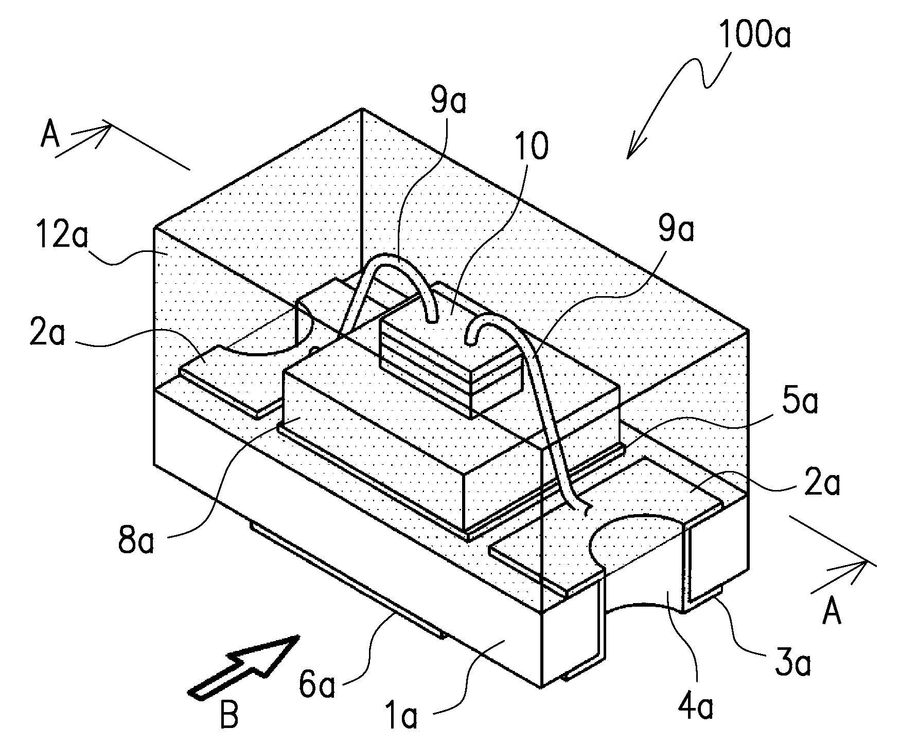
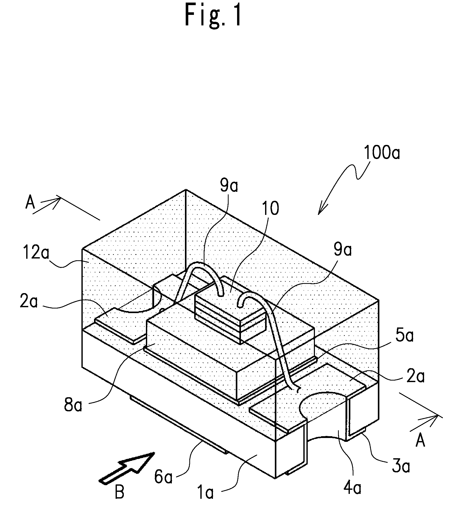
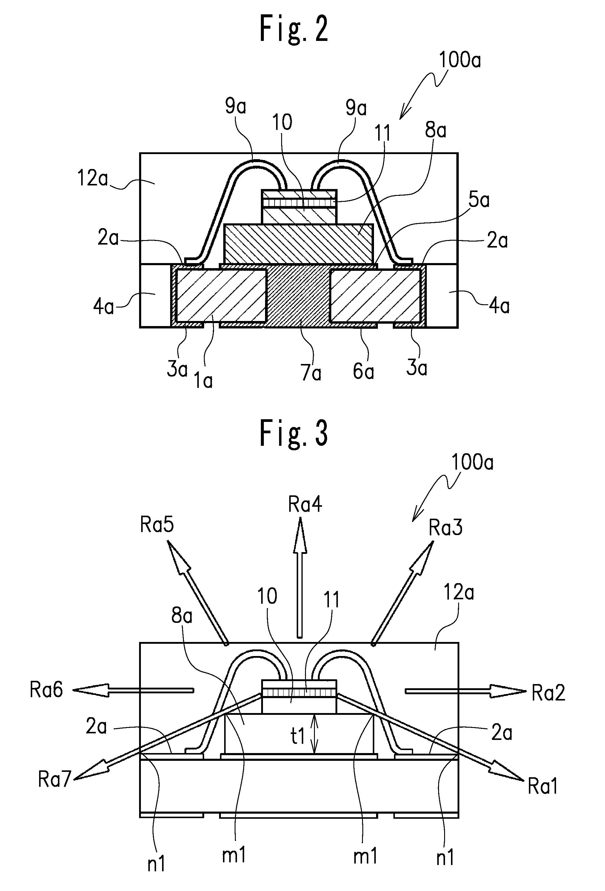
[0025]FIGS. 1 to 3 illustrate a light-emitting diode (hereinafter, referred to as LED) according to a first embodiment of the present invention.

[0026]The LED 100a in the first embodiment includes a circuit board 1a, a heat-dissipation plate 8a provided on one surface, for example, an upper surface (as viewed in FIG. 2) of the circuit board 1a, at least one light-emitting diode element (hereinafter, referred to as LED element) 10 provided on the heat-dissipation plate 8a, and a light-transmitting resin 12a provided on the upper surface of the circuit board 1a to seal the LED element (see FIG. 1).

[0027]A pair of electrodes that are electrically connected to the LED element 10 are provided adjacent to opposite sides on the circuit board 1a. The pair of electrodes in an embodiment comprise, for example, a pair of upper electrodes 2a provided at opposite ends of the upper surface of the circuit board 1a, the LED element 10 being disposed between the pair of upper electrod...

Example

Second Embodiment

[0044]Next, a second embodiment of the LED according to the present invention is described.

[0045]FIGS. 4 to 6 illustrate a structure of an LED 100b according to the second embodiment of the present invention.

[0046]A first point in which the LED 100b in the second embodiment differs from the LED 100a in the first embodiment is in that a step 13 is provided on a circumferential edge portion of a circuit board 1b similar to the circuit board 1a. According to the provision of the step 13, a structure and a shape of electrodes, and an external shape of a heat-dissipation plate 8b slightly differ from the electrodes and the heat-dissipation plate 8a, respectively.

[0047]As shown in FIG. 4, in the LED 100b, a light-transmitting resin 12b is configured to seal an upper surface of the circuit board 1b, the step 13, upper electrodes 2b, an upper central electrode 5b for heat-dissipation on which an LED element 10 is disposed, the heat-dissipation plate 8b, the LED element 10 a...

Example

Third Embodiment

[0059]Next, a third embodiment to realize an LED of an even higher output or higher watt type, according to the present invention is described.

[0060]FIG. 7 illustrates a structure of an LED 100c according to the third embodiment of the present invention. Because the LED 100c is the same in basic structure as the LED 100a in the first embodiment as shown in FIG. 1, identical reference numbers are attached to similar parts to those in the first embodiment, and a repeated description is omitted.

[0061]A point in which the LED 100c differs from the LED 100a is in that a plurality of LED elements 10 are disposed on and fixed to a heat-dissipation plate 8c. An external dimension of each of the heat-dissipation plate 8c, the circuit board 1c, the electrodes of this embodiment is configured to be larger than the respective those of the heat-dissipation plate 8a, the circuit board 1a, the electrode terminals, and so on, as shown in FIG. 1, because a plurality of LED elements 1...


PUM


Abstract

A light-emitting diode includes a circuit board, a pair of electrodes provided on the circuit board, at least one light-emitting diode element electrically connected to the pair of electrodes, a central electrode for heat-dissipation, provided between the pair of electrodes on the circuit board, and a heat-dissipation plate disposed on the central electrode for heat-dissipation and including a reflection surface. The central electrode for heat-dissipation includes an upper central electrode disposed on the upper surface of the circuit board and a lower central electrode disposed on the lower surface of the circuit board and the upper central electrode thermally connected to the lower central electrode.

Description

CROSS-REFERENCE TO THE RELATED APPLICATION[0001]The application is based on and claims the priority benefit of Japanese Patent Application No. 2008-246580, filed on Sep. 25, 2008, the entire descriptions of which are incorporated herein by reference.BACKGROUND OF THE INVENTION[0002]1. Field of the Invention[0003]The present invention relates to a light-emitting diode (LED) capable of being mounted on a motherboard of lighting devices, information terminal devices or the like, more specifically to an LED for illumination having, in particular, high brightness and excellent heat-dissipation properties.[0004]2. Description of the Related Art[0005]LEDs have been widely employed in various electrical devices as small electronic parts for illumination due to their long operational life, small size, high emission efficiency, low power consumption or the like.[0006]LEDs can be easily solder-mounted on a surface of a motherboard of the devices by using a mounter and achieve an excellent mass...

Claims


Application Information

Patent Timeline
IPC IPC(8): H01L33/00
CPCH01L25/0753H01L33/486H01L33/642H01L2224/48091H01L2224/48227H01L2224/48235H01L2224/73265H01L2924/3025H01L2224/45144H01L2224/49113H01L2924/00014H01L2924/00
Inventor KADOTANI, NORIKAZU
Owner CITIZEN ELECTRONICS CO LTD
Why Eureka
Try Eureka