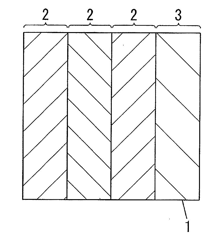
Light emitting device
- Summary
- Abstract
- Description
- Claims
- Application Information
AI Technical Summary
Benefits of technology
Problems solved by technology
Method used
Image
Examples
example 1
[0116]A first composition was prepared, containing a nematic liquid crystal substance (manufactured by Merck, product no. E44), a chiral agent (manufactured by Merck, product no. S-811), and a photo-polymerization starting agent (manufactured by BASF; product name: IRGACURE 184). The concentration of the chiral agent in the first composition was 30% by mass, and the concentration of the photo-polymerization starting agent was 2% by mass.
[0117]A second composition was prepared, containing a nematic liquid crystal substance (manufactured by Merck, product no. E44), and a photo-polymerization starting agent (manufactured by BASF; product name: IRGACURE 184). The concentration of the photo-polymerization starting agent in the second composition was 2% by mass.
[0118]An organic EL element (light-emission wavelength region: 480 to 680 nm) equipped with a second electrode comprising an IZO film of 100 nm in thickness was prepared. A polyimide orientation material (manufactured by JSR Corpor...
example 2
[0123]A third composition was prepared, containing a chiral smectic liquid crystal comprising a mixture from 49.2% by mass of 2-(4-hexyloxy-phenyl)-5-octyl-pyrimidine, 25.1% by mass of 5-hexyl-2-(4′-pentyl-biphenyl-4-yl)-pyrimidine, and 25.6% by mass of [1,1′,4,1″]terphenyl-4,4″-dicarboxylic acid bis-(1-methyl-heptyl)ester, as well as a photo-polymerization starting agent (manufactured by BASF; product name: IRGACURE 184). The concentration of the photo-polymerization starting agent in the third composition was 2% by mass.
[0124]Molecular orientation layers were formed by coating and forming into films a polyimide orientation material (manufactured by JSR Corporation; product no. JALS-2021-R2) on two glass plates, respectively. A rubbing treatment was further performed on these molecular orientation layers. These two molecular orientation films were placed so as to be in opposition, and a 50 μm-thick spacer was intercalated between the two parties.
[0125]The third composition was fill...
example 3
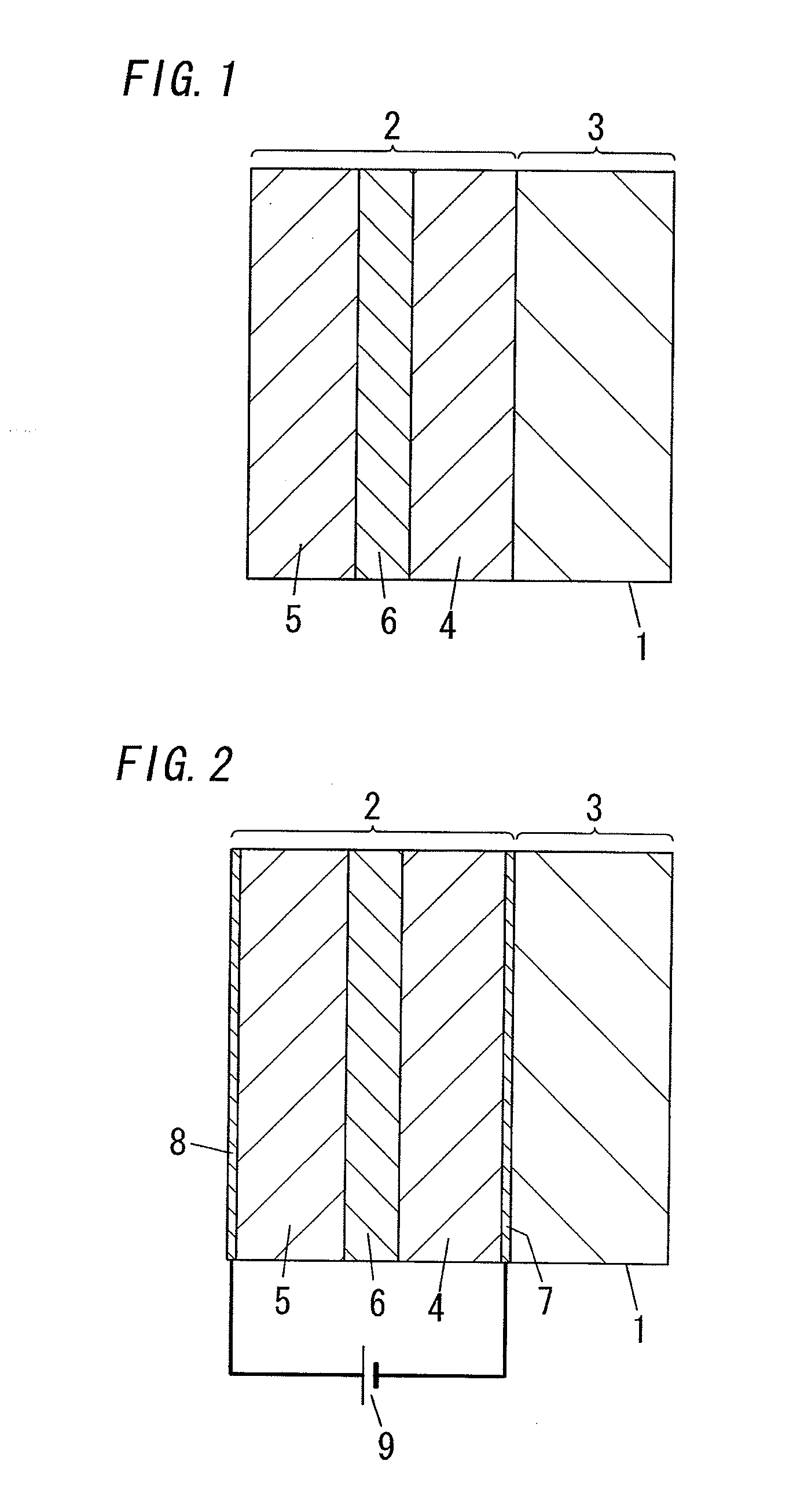
[0130]After a third layer was formed between the first layer and the second layer in Example 1, transparent electrodes for external field control means were formed on the external surface of the first layer and on the external surface of the second layer, respectively. Otherwise, a light-emitting device was obtained by the same methods as Example 1.
[0131]The selective reflection wavelength regions of the first layer and the second layer in the reflective layer of this light-emitting device were 570 to 640 nm (that is to say, the wavelength region of the specific light was 570 to 640 nm).
[0132]When the molecular orientation of the third layer in this light-emitting device was in the first state, the reflectance of specific light by the reflective layer was 88%, and the transmittance of the light-emitting device for white light was 80%. Meanwhile, when the molecular orientation of the third layer in this light-emitting device was switched to the second state by the external field cont...
PUM
 Abstract
Description
Claims
Application Information
 - R&D
- Intellectual Property
- Life Sciences
- Materials
- Tech Scout
- Unparalleled Data Quality
- Higher Quality Content
- 60% Fewer Hallucinations
Browse by: Latest US Patents, China's latest patents, Technical Efficacy Thesaurus, Application Domain, Technology Topic, Popular Technical Reports.
© 2025 PatSnap. All rights reserved.Legal|Privacy policy|Modern Slavery Act Transparency Statement|Sitemap|About US| Contact US: help@patsnap.com


