Electronic circuit for driving a diode load

a technology of electronic circuits and diodes, applied in the direction of electric variable regulation, process and machine control, instruments, etc., can solve the problems of reducing power dissipation, unnecessarily high power dissipation of boost switching regulators, and above-described electronic techniques can also suffer high power dissipation, so as to achieve rapid stabilization of the control loop of the boost switching regulators. , the effect of audible nois

Active Publication Date: 2010-03-25
ALLEGRO MICROSYSTEMS INC
View PDF44 Cites 46 Cited by
  • Summary
  • Abstract
  • Description
  • Claims
  • Application Information

AI Technical Summary

Benefits of technology

[0011]With the above arrangements, open circuit protection is provided by which an open load element or elements coupled to the current regulator is detected and decoupled from the electronic circuit, as may include a boost switching regulator for driving the load, via opening of a respective switch. This arrangement is particularly advantageous in embodiments in which the electronic circuit includes a boost switching regulator that receives, as a feedback, the signal at one or more of the current regulator current sense nodes, since otherwise, an open circuit load condition could cause the switching regulator output voltage to increase excessively as may damage other components and cause significant power dissipation. Advantageously, the open circuit load is not disabled, but simply decoupled from the circuit, thereby permitting the faulty load to again be coupled to the circuit if the fault is temporary.
[0012]In some embodiments, the open-circuit detection circuit is configured to open the switch in response to both the signal at the current sense node of the current regulator being below the first predetermined current threshold and the occurrence of another condition, such as an over-voltage condition and / or an over-temperature condition. This arrangement prevents false, perhaps transient, indications of the current regulator current being below the first predetermined current threshold from opening the switch.
[0014]With this arrangement, a simple short circuit protection scheme is provided whereby the switch is closed during normal operation and open when a short circuit condition occurs. The current-passing circuit allows the electronic circuit to start up and to resume operation following removal of a short circuit condition by allowing a small current to pass. This arrangement is possible because the diode load draws very little current until the switching regulator output voltage reaches a sufficient voltage.
[0016]With this arrangement, the output voltage of the switching regulator is held substantially constant during intervals when the current regulators are disabled by the pulse width modulation. Audible noise that may otherwise be generated due to voltage swings on ceramic capacitors is reduced or eliminated.
[0017]In some embodiments, a capacitor is coupled to the control node of the boost switching regulator through a switch that is controlled by the pulse width modulation circuit such that the switch is closed when the current regulator is enabled and open when the current regulator is disabled. With this arrangement, the voltage at the control input to the switching regulator is held substantially constant, at its previous voltage level, during intervals in which the current regulators are disabled by the pulse width modulation circuit, thereby resulting in rapid stabilization of the boost switching regulator control loop during each pulse width modulation cycle.

Problems solved by technology

While it is possible to provide a fixed voltage boost switching regulator that can supply enough voltage for all possible series strings of LEDs, such a boost switching regulator would generate unnecessarily high power dissipation when driving strings of series connected LEDs having less voltage drop.
While the above-described electronic technique can result in a reduction of power dissipation, the above-described electronic technique can also suffer a high power dissipation if one of the series connected strings of LEDs becomes open circuit, i.e., fails.
In this situation, a high voltage drop would be sensed and the common boost switching regulator would be controlled to increased its output voltage as high as it is able, resulting in a higher power dissipation associated with the remaining strings of series connected LEDs.

Method used


Image

  • Electronic circuit for driving a diode load
  • Electronic circuit for driving a diode load
  • Electronic circuit for driving a diode load

Examples


Embodiment Construction

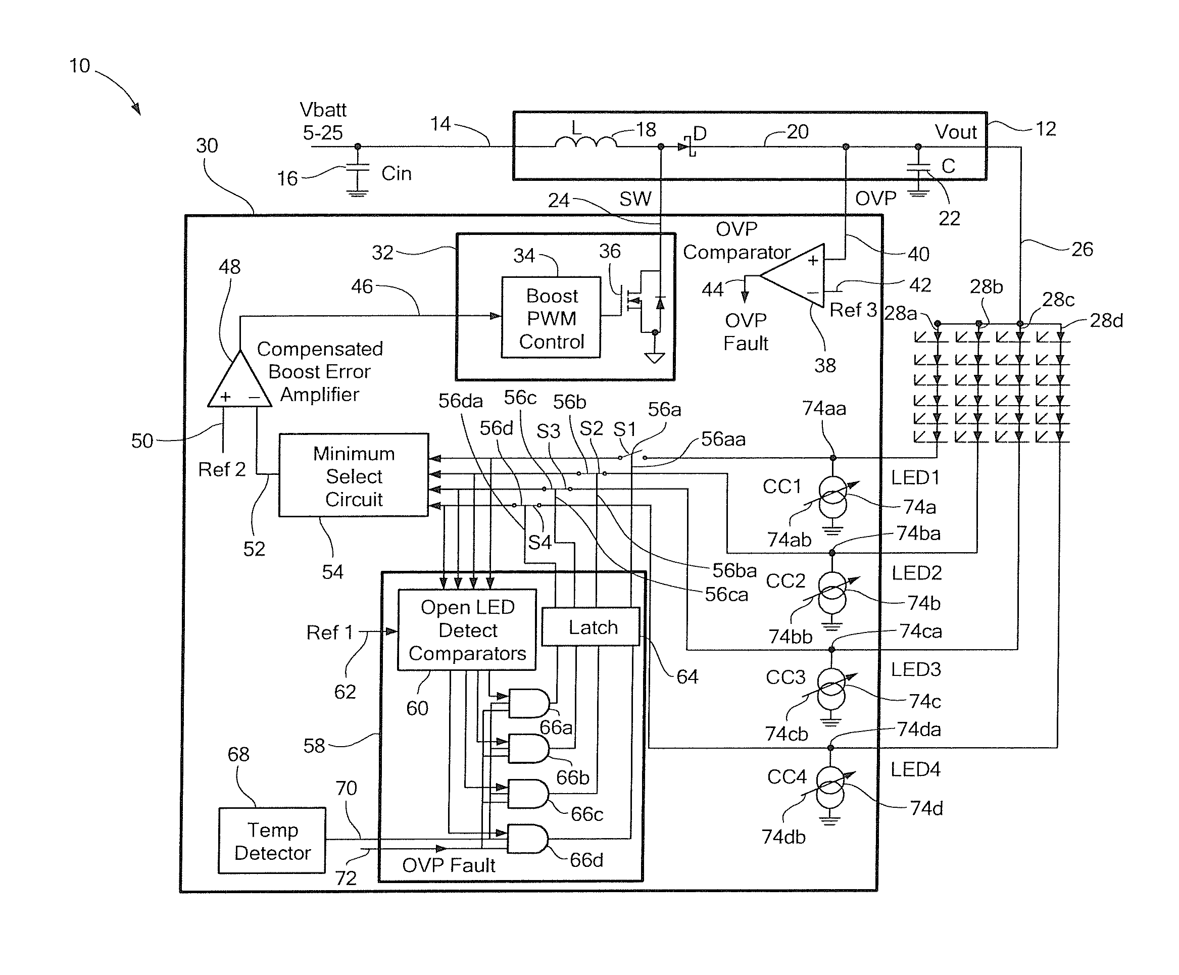
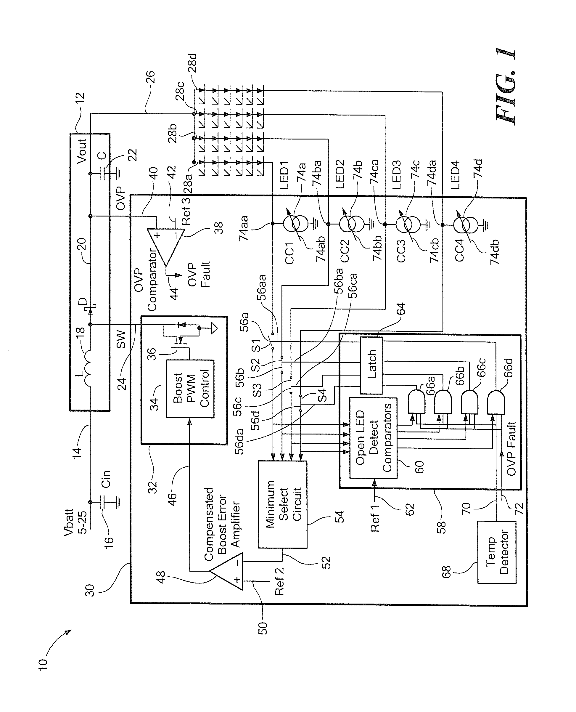
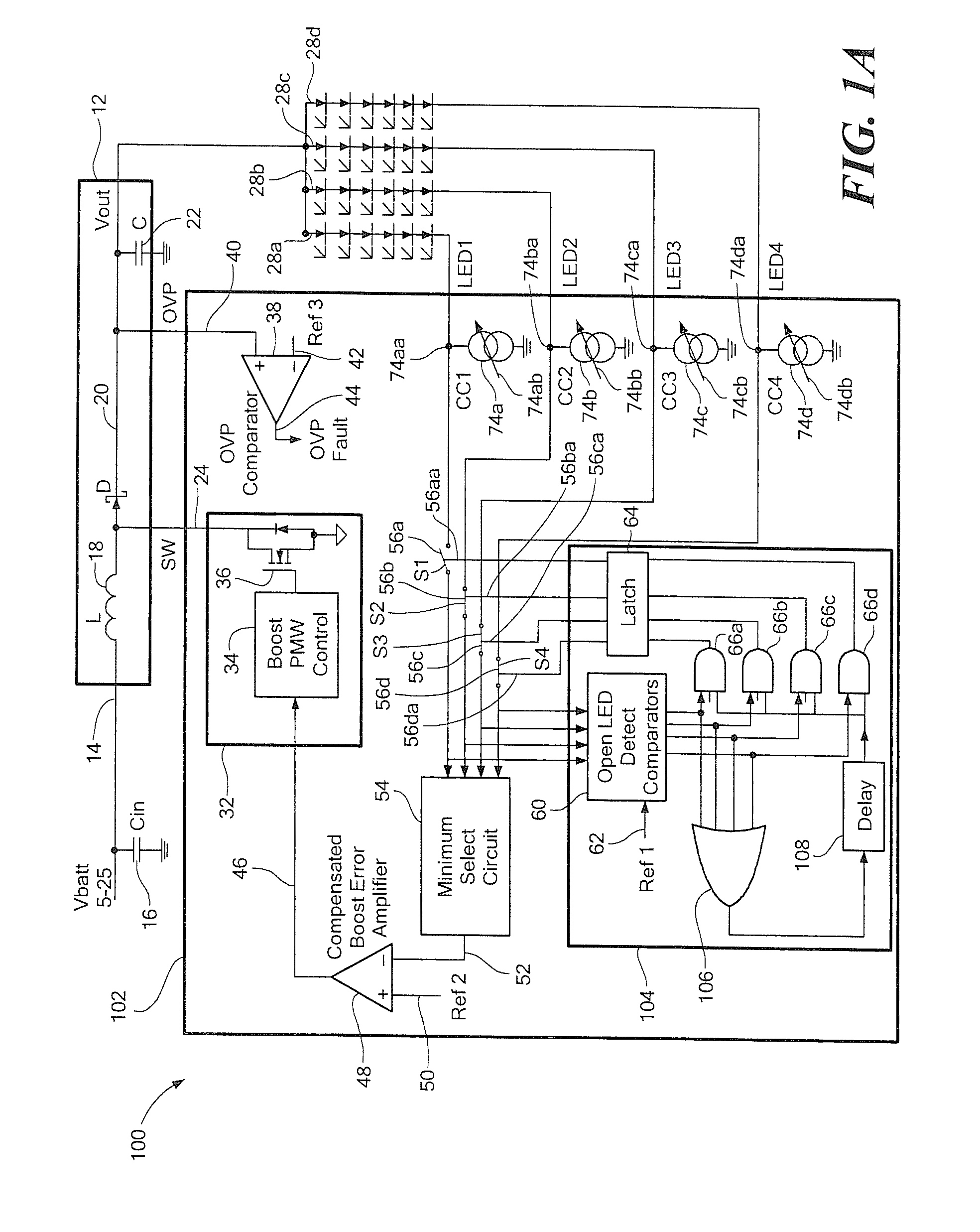
[0025]Before describing the present invention, some introductory concepts and terminology are explained. As used herein, the term “boost switching regulator” is used to describe a known type of switching regulator that provides an output voltage higher than an input voltage to the boost switching regulator. While a certain particular circuit topology of boost switching regulator is shown herein, it should be understood that a boost switching regulator can be formed in a variety of circuit configurations.

[0026]As used herein, the term “current regulator” is used to describe a circuit or a circuit component that can regulate a current passing through the circuit or circuit component to a predetermined, i.e., regulated, current. A current regulator can be a “current sink,” which can input a current, or a “current source,” which can output a regulated current. A current regulator has a “current node” at which a current is output in the case of a current source, or at which a current is ...


PUM


Abstract

An electronic circuit includes circuit portions for identifying a largest voltage drop through one of a plurality of series connected diode strings and for controlling a boost switching regulator according to the largest voltage drop. The electronic circuit can sense an open circuit series connected diode string, which would otherwise have the largest voltage drop, and can disconnect that open circuit series connected diode string from control of the boost switching regulator. Another electronic circuit includes a current limiting circuit coupled to or within a boost switching regulator and configured to operate with a diode load. Another electronic circuit includes a pulse width modulation circuit configured to dim a series connected string of light emitting diodes.

Description

CROSS REFERENCE TO RELATED APPLICATIONS[0001]This application a Divisional Application of and claims the benefit of U.S. patent application Ser. No. 11 / 619,675 filed Jan. 4, 2007, which is incorporated herein by reference in its entirety.STATEMENT REGARDING FEDERALLY SPONSORED RESEARCH[0002]Not Applicable.FIELD OF THE INVENTION[0003]This invention relates generally to electronic circuits and, more particularly, to electronic circuits used to drive a light emitting diode (LED) load.BACKGROUND OF THE INVENTION[0004]A variety of electronic circuits are used to drive diode loads and, more particularly, to control electrical current through strings of series connected light-emitting diodes (LEDs), which, in some embodiments, form an LED display. It is known that individual LEDs have a variation in forward voltage drop from unit to unit. Therefore, the strings of series connected LEDs can have a variation in forward voltage drop.[0005]Strings of series connected LEDs can be coupled to a c...

Claims


Application Information

Patent Timeline
Patent Type & Authority Applications(United States)
IPC IPC(8): H05B41/36H05B44/00
CPCG05F1/46
Inventor SZCZESZYNSKI, GREGORYWEKHANDE, SHASHANKMANGTANI, VIJAY
Owner ALLEGRO MICROSYSTEMS INC
Why Eureka
Try Eureka