Magnetic field sensor array for measuring spatial components of a magnetic field

Active Publication Date: 2010-03-25
ROBERT BOSCH GMBH
View PDF2 Cites 22 Cited by
  • Summary
  • Abstract
  • Description
  • Claims
  • Application Information

AI Technical Summary

Problems solved by technology

One disadvantage of the sensor arrays with the XMR effect is that in contrast to Hall sensors, they are sensitive to the magnetic flux density in the plane of the magnetoresistive film structures.
However, if the greater magnetic field sensitivity of the magnetic field sensors is to be employed, utilizing the XMR effect, for direct determination of the vertical magnetic field component, then thus far in this respect it can be learned from European Patent Disclosure EP 1 860 451 A1 only that a projection of the vertical magnetic field component onto a beveled substrate face of the semiconductor chip can be detected, which means complicated production of the substrate with precise control of the substrate angle, so that then a conclusion can be drawn about the true vertical magnetic field component.

Method used


Image

  • Magnetic field sensor array for measuring spatial components of a magnetic field
  • Magnetic field sensor array for measuring spatial components of a magnetic field
  • Magnetic field sensor array for measuring spatial components of a magnetic field

Examples


Embodiment Construction

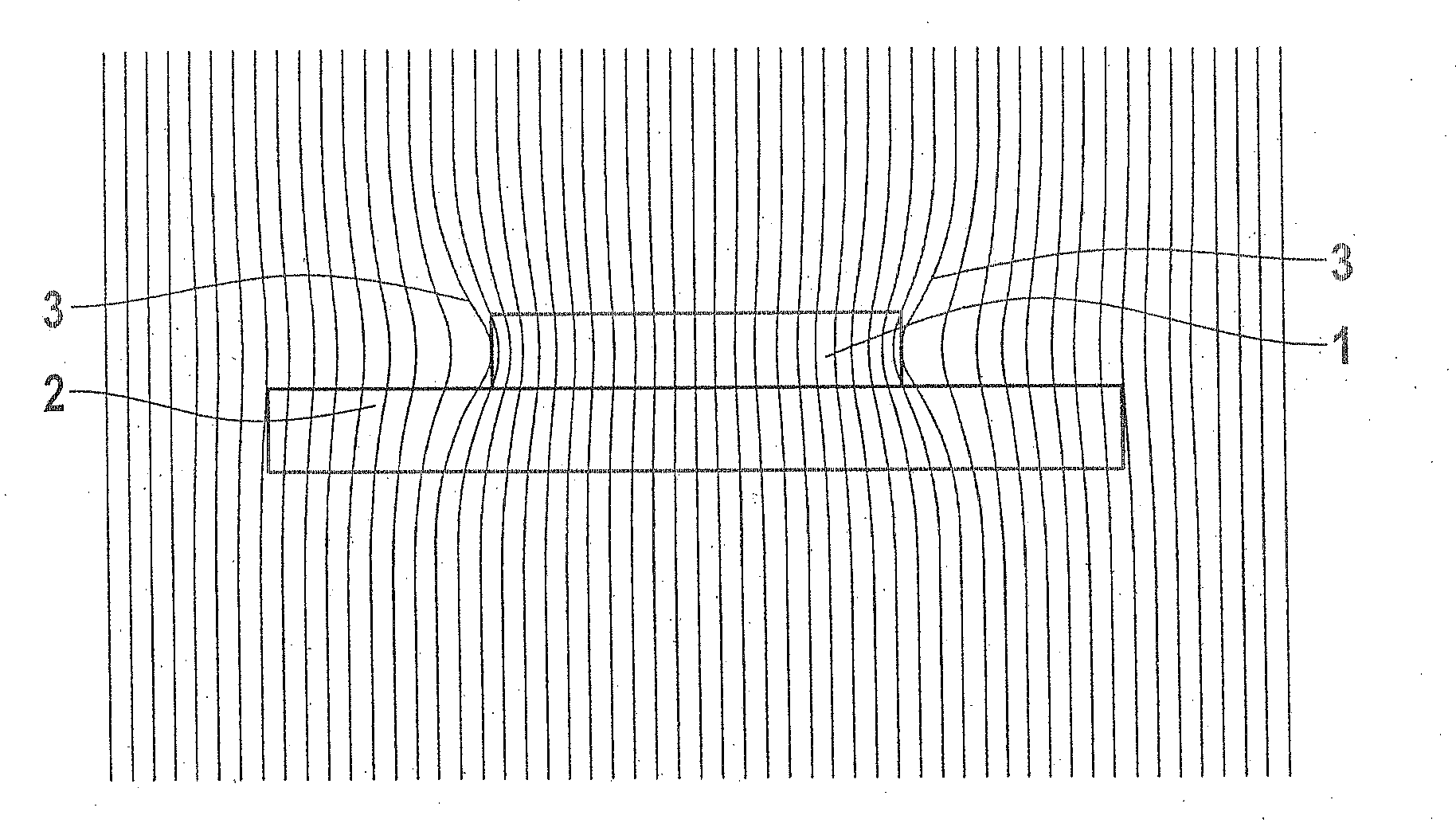
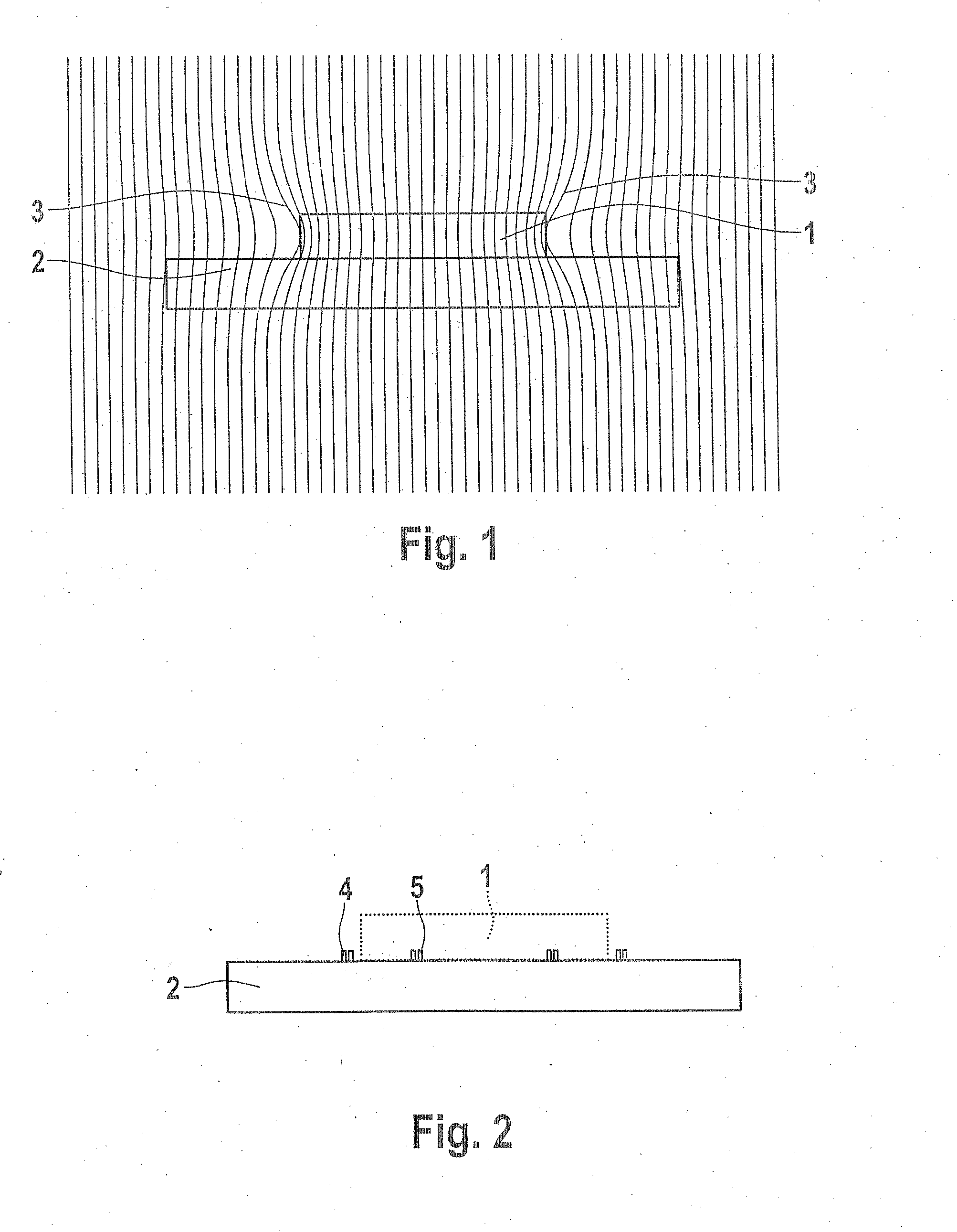
[0026]A magnetic field array schematically shown in FIG. 1 comprises a soft-magnetic flux concentrator 1, which is located on the surface of a substrate, in this case a semiconductor chip 2, as a carrier of magnetic field sensors, such as GMR sensors. From FIG. 1, it can be seen that field lines 3 of a magnetic field to be detected are for example deflected on the peripheral region of the flux concentrator 1 out of their originally vertical direction into a horizontal direction, so that they become measurable for the magnetic field sensors.

[0027]Since the lengths of the field lines 3 in the material comprising the flux concentrator 1 for the vertical-to-horizontal deflection are shorter than the length for the horizontal-to-vertical deflection, the result is admittedly a slight deflection effect, but that can be compensated for by the increased sensitivity of the magnetic field sensors. To enhance the measurement effect, the flux concentrator 1 could possibly be countersunk in a man...


PUM


Abstract

A magnetic field array for measuring spatial components of a magnetic field is proposed, in which with at least one magnetic field sensor utilizing the XMR effect in a magnetoresistive film structure, a further component, perpendicular or nonparallel to the film structure of the magnetic field to be detected, is detectable in that at least one flux concentrator is disposed above the film structure in such a way that the magnetic field lines in the peripheral regions of the flux concentrator are deflectable in such a way that there, the field lines embody a horizontal component of the magnetic field.

Description

CROSS-REFERENCE TO RELATED APPLICATION[0001]This application is based on German Patent Application 10 2008 041 859.5 filed Sep. 8, 2008.BACKGROUND OF THE INVENTION[0002]1. Field of the Invention[0003]The invention relates to a magnetic field array for measuring spatial components of a magnetic field.[0004]2. Description of the Prior Art[0005]It is generally known that in rpm and position sensors, for instance, such as are used for controlling motors or in transmission or vehicle dynamics controls in motor vehicles, a rotary motion or change of position is detected by means of a magnetic field variation that corresponds to the rotation or the change of position. Then as a rule, magnet sensors known per se are employed, which depending on the application and field of use may be Hall sensors or magnetoresistive sensors.[0006]Besides magnetoresistive structures that are based on the anisotropic magnetic resistance effect (AMR), the more-sensitive giant magnetoresistance structures (GMRs...

Claims


Application Information

Patent Timeline
Patent Type & Authority Applications(United States)
IPC IPC(8): G01R33/00
CPCG01R33/093B82Y25/00
Inventor BAUER, CHRISTIAN
Owner ROBERT BOSCH GMBH
Why Eureka
Try Eureka