Liquid crystal display device, television receiver, and lighting device

a technology of liquid crystal display and television receiver, which is applied in the direction of television system details, instruments, television systems, etc., can solve the problems of inability to appropriately correct the display image error, and achieve the effect of suppressing reducing the influence of cross talk on the display image, and easy and accurate control of the light intensity of the light source uni

Active Publication Date: 2010-03-25
SHARP KK
View PDF11 Cites 11 Cited by
  • Summary
  • Abstract
  • Description
  • Claims
  • Application Information

AI Technical Summary

Benefits of technology

[0017]As illustrated in (c) of FIG. 20, in the liquid crystal display device in which the luminance of the backlight is not controlled, luminances of the respective lighting regions are uniform, so that a display luminance of the black display part is determined only by the contrast CR of the liquid crystal panel. Meanwhile, in the liquid crystal display device in which a luminance of a backlight is controlled (in a liquid crystal display device in which a luminance of each lighting region is controlled), a luminance of a black display part is determined by the contrast CR of the liquid crystal panel and spatial distribution of a light luminance of the backlight, so that it is possible to effectively improve the contrast. However, on the other hand, the luminance of the black display part of the image displayed in the liquid crystal display device varies depending on a position (distance from the white display part). As the position is further away from the white display part, the luminance becomes lower.
[0039]With the arrangement, each of the lighting regions has a smaller width in the left-and-right direction than in the up-and-down direction, so that it is possible to cause a part between the lighting regions, where the cross talk occurs, to spread narrower in the left-and-right direction than in the up-and-down direction. Thereby, it is possible to (i) cause a reduction in contrast due to spatial distribution of light luminances, which spatial distribution is generated due to cross talk between lighting regions, to be less perceivable to an observer positioned in a wide viewing angle range in the left-and-right direction, and thereby (ii) provide the observer with a high quality image.

Problems solved by technology

However, in the technique of Patent Literature 1, although the correction look-up table is used to correct the error of the display image due to spatial distribution of the light luminances, which spatial distribution is generated due to cross talk of light between the lighting regions, this method may fail to appropriately correct the error of the display image as described below.

Method used


Image

  • Liquid crystal display device, television receiver, and lighting device
  • Liquid crystal display device, television receiver, and lighting device
  • Liquid crystal display device, television receiver, and lighting device

Examples


embodiment 1

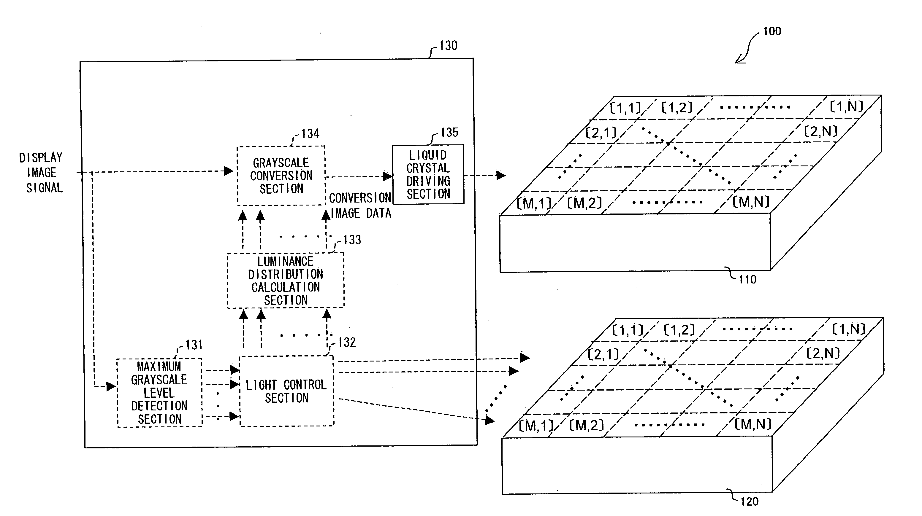
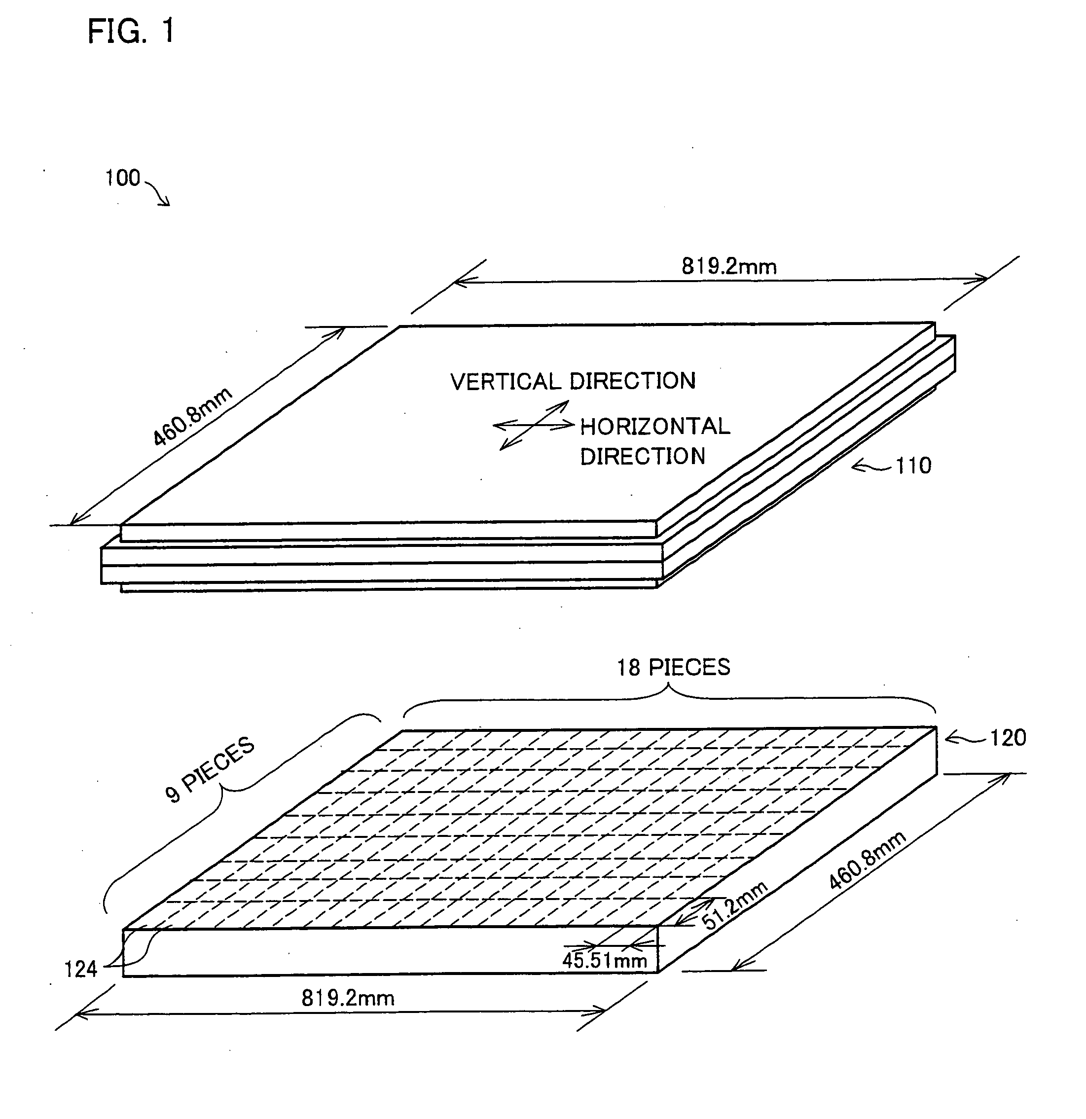
[0117]One embodiment of the present invention is described below. FIG. 1 is a view schematically illustrating a configuration of a liquid crystal display device 100 in accordance with the present embodiment. As illustrated in FIG. 1, the liquid crystal display device 100 includes a liquid crystal panel 110 and a backlight unit 120. Further, the liquid crystal display device 100 is provided to a television receiver and displays an image of a television broadcast (input image signal) received by a receiving device (not illustrated).

[0118]The liquid crystal panel 110 is an IPS-mode liquid crystal panel. However, any transmissive liquid crystal panel may be used as the liquid crystal panel 110 as long as the transmissive liquid crystal panel can carry out multiple grayscale display. For example, it is possible to adopt a liquid crystal panel in another mode such as a TN mode, a VA mode, an OCB mode, or the like. Note that, a conventionally known liquid crystal panel can be used as the l...

embodiment 2

[0154]Another embodiment of the present invention is described below. FIG. 11 is a view schematically illustrating a configuration of a liquid crystal display device 200 in accordance with the present embodiment. As illustrated in FIG. 11, the liquid crystal display device 200 includes a liquid crystal panel 210 and a backlight unit 220. Further, the liquid crystal display device 200 is provided to a television receiver and displays an image of a television broadcast received by a receiving device (not illustrated).

[0155]As the liquid crystal panel 210, a VA-mode liquid crystal panel is used. However, the configuration is not limited to this as long as the liquid crystal panel 210 is a transmissive liquid crystal panel which can carry out multiple grayscale display. For example, it is possible to use a liquid crystal panel in another mode such as TN mode, VA mode, OCB mode, or the like. Note that, a publicly known liquid crystal panel can be used as the liquid crystal panel, so that...


PUM

PropertyMeasurementUnit
viewing anglesaaaaaaaaaa
sizeaaaaaaaaaa

Abstract

In an embodiment of the present invention, in a liquid crystal display device which controls a light luminance of each of lighting regions, each of lighting regions of a backlight has a smaller width in a horizontal direction than in a vertical direction. This makes it possible to cause a reduction in contrast due to spatial distribution of light luminances, which spatial distribution is generated due to cross talk between lighting regions, to be less perceivable to an observer positioned in an oblique viewing direction.

Description

TECHNICAL FIELD[0001]The present invention relates to a liquid crystal display device including a liquid crystal display panel and a backlight (lighting device). More specifically, the present invention relates to a liquid crystal display device which controls light from a backlight in accordance with a display image so that an observer more clearly feels contrast.BACKGROUND ART[0002]A liquid crystal display device is characterized by its thinness, low power consumption, high definition and the like, and, as a production technique of the liquid crystal display device has been developed, it becomes possible to manufacture a large-screen liquid crystal display device. Consequently, the liquid crystal display device becomes popular in a television field which has been occupied mainly by a cathode ray tube (CRT).[0003]However, due to a display method of the liquid crystal display device, an image displayed in the liquid crystal display device has such a problem that the observer less cl...

Claims


Application Information

Patent Timeline
Patent Type & Authority Applications(United States)
IPC IPC(8): G02F1/13357
CPCG02F2001/133601G09G3/3426G09G3/3611H04N5/66G09G2320/028G09G2320/0646G09G2320/0209G02F1/133601
Inventor MASUDA, TAKESHI
Owner SHARP KK
Why Eureka
Try Eureka