
Light guide plate, backlight module and liquid crystal display

a technology of backlight module and light guide plate, which is applied in the direction of instruments, lighting and heating apparatus, optical elements, etc., can solve the problems of difficult control of the brightness and uniformity of backlight module light, and achieve the effect of improving the ability of light concentration

Active Publication Date: 2010-03-25
AU OPTRONICS CORP
View PDF16 Cites 7 Cited by
  • Summary
  • Abstract
  • Description
  • Claims
  • Application Information

AI Technical Summary

Benefits of technology

"The present invention provides a light guide plate with improved light concentration, higher light output efficiency, and better ability to concentrate light. The light guide plate also maintains symmetrical light output at parallel viewing angles and reduces the usage number of optical films. This is achieved by a first surface with at least one first structure and at least one second structure, where the first structure includes at least one first protrusion with a cross section of an eccentric triangle, and the second structure includes at least one second protrusion with a cross section of an eccentric triangle."

Problems solved by technology

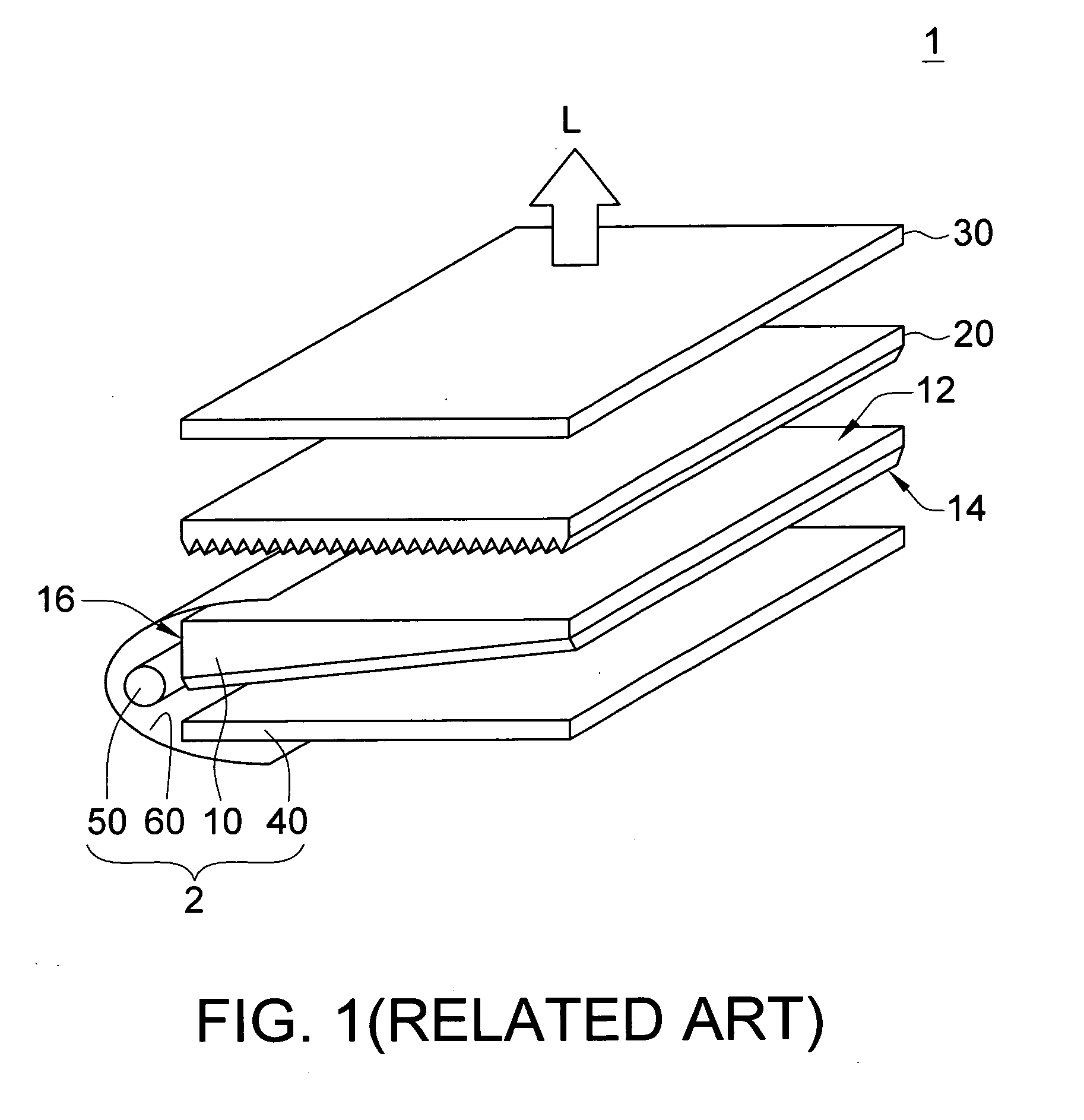
However, because of the optical film 20, it is difficult to control the brightness and uniformity of the light from the backlight module 2.

Method used


Image

  • Light guide plate, backlight module and liquid crystal display
  • Light guide plate, backlight module and liquid crystal display
  • Light guide plate, backlight module and liquid crystal display

Examples


Embodiment Construction

[0019]Reference will now be made in detail to the present preferred embodiments of the invention, examples of which are illustrated in the accompanying drawings. Wherever possible, the same reference numbers are used in the drawings and the description to refer to the same or like parts.

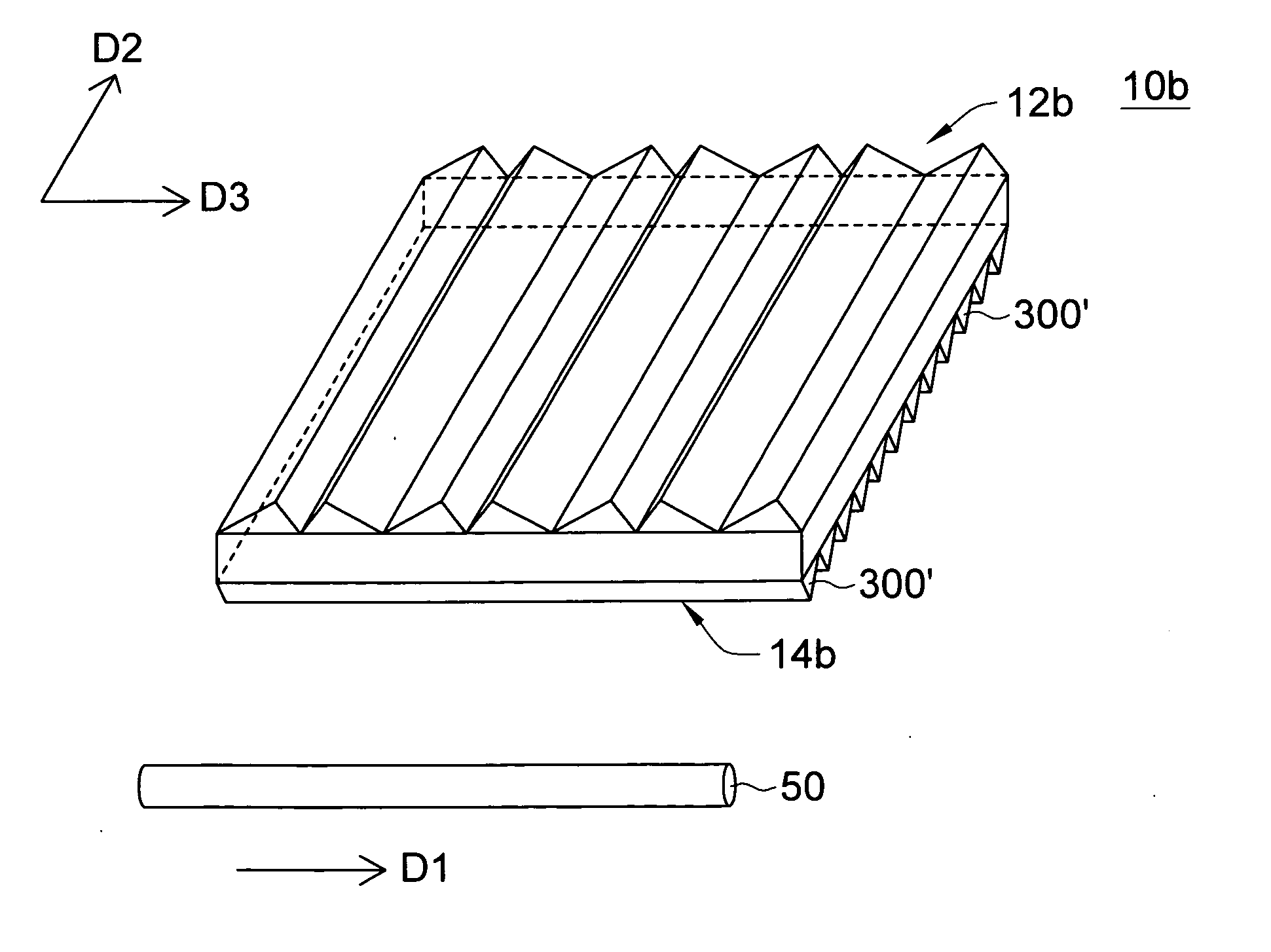
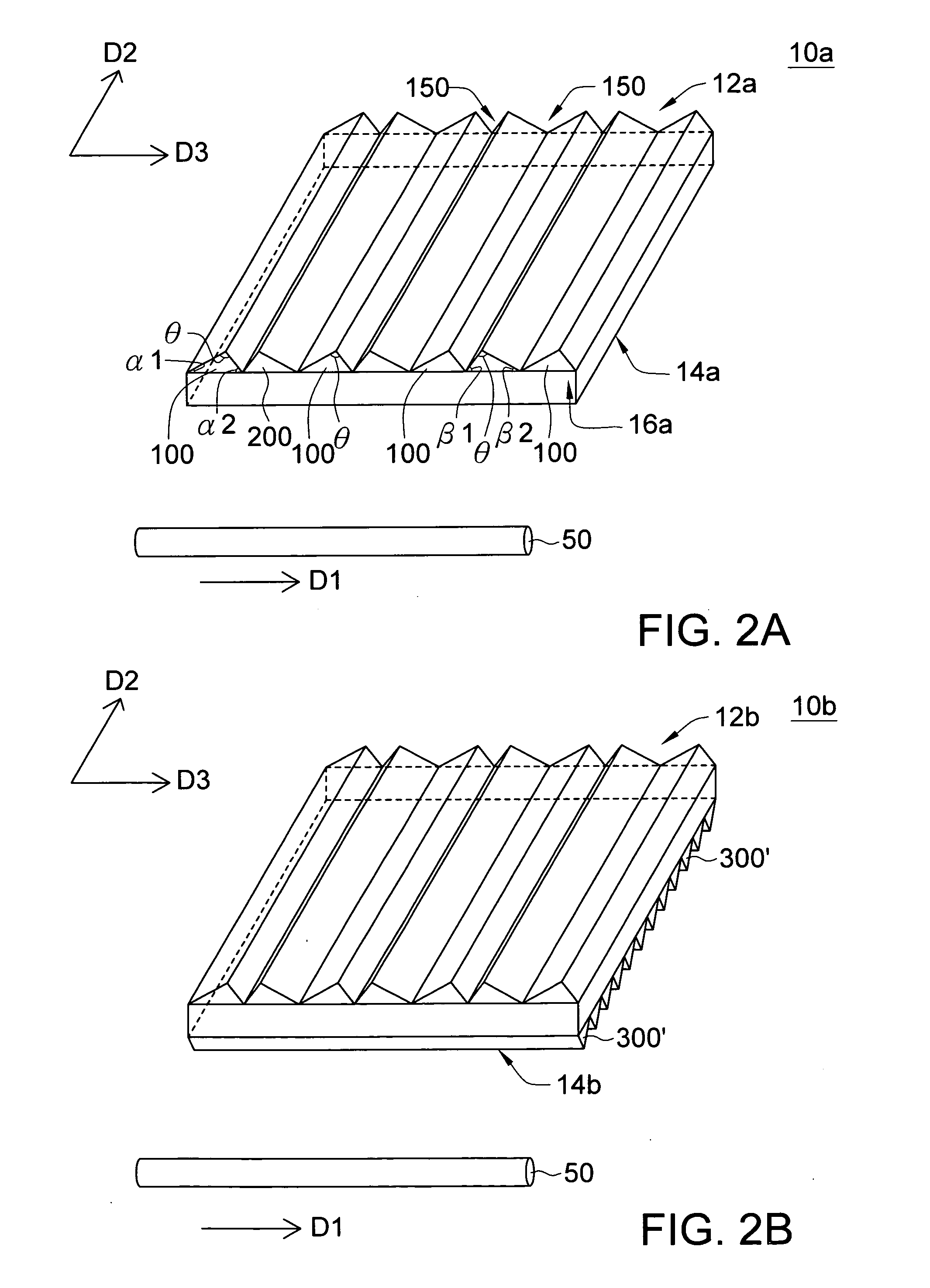
[0020]FIGS. 2A to 13 show light guide plates according to the embodiments of the present invention. For easy to understand and explanation, light source 50 is added therein to show the location relationship with the light guide plate. Location relationships among the light guide plate, the reflector, the optical films and the liquid crystal display panel can be referred to FIG. 1, which people of ordinary skill in the art can understand, but not limited thereto.

[0021]As shown in FIG. 2A, light guide plate 10a has upper surface 12a at least with first structure 100 and second structure 200. In the present embodiment, first structures 100 and second structures 200 are plural, for example, but not limit...


PUM

PropertyMeasurementUnit
top angleaaaaaaaaaa
bottom anglesaaaaaaaaaa
angleaaaaaaaaaa

Abstract

A light guide plate, a backlight module and a liquid crystal display are provided. The light guide plate has a first surface at least having one first structure and one second structure formed thereon. The first structure and the second structure are adjacent arranged and are mirror reflection with each other. Each of the first structure and the second structure has a first protrusion having a cross section of eccentric triangle.

Description

[0001]This application claims the benefit of Taiwan Patent Application Serial No. 97136370, filed Sep. 22, 2008, the subject matter of which is incorporated herein by reference.BACKGROUND OF THE INVENTION[0002]1. Field of the Invention[0003]The present invention generally relates to a light guide plate, backlight module and a liquid crystal display, and especially relates to a light guide plate, a backlight module and a liquid crystal display using the same with higher luminance, light outputting efficiency and light concentration.[0004]2. Description of Related Art[0005]A liquid crystal display which can produce colorful image has been applied broadly to notebook computer, personal digital assistant and desktop and replaced traditional cathode ray tube display, because of its lightweight, lower power consumer and low radiation pollution.[0006]FIG. 1 shows a conventional liquid crystal display (LCD). LCD 1 comprises backlight module 2, optical film 20 and liquid crystal display pane...

Claims


Application Information

Patent Timeline
Patent Type & Authority Applications(United States)
IPC IPC(8): G02F1/13357G02B6/10G09F13/04
CPCG02B6/0036G02F1/133615G02B6/0038
Inventor YEH, YAO-CHUNG
Owner AU OPTRONICS CORP
Learn More