Oil pump for a refrigerating compressor

Inactive Publication Date: 2010-03-25
WHIRPOOL SA
4 Cites 14 Cited by

AI-Extracted Technical Summary

Problems solved by technology

This solution allows friction wear to occur between the parts of pump body and tubular sleeve, as well as mechanical losses, as a result of the rigid fixation between said tubular sleeve and the stator and of practically inevitable misalignments between the pump body and the tubular sleeve.
However, as the pump body is not free to be displaced, in its entirety, in directions orthogonal to the crankshaft, it i...

Benefits of technology

[0012]It is an object of the present invention to provide an oil pump for a refrigerating compressor, which g...

Abstract

Oil pump for hermetic refrigerating compressor comprising a tubular sleeve having an upper portion affixed to at least one of the parts of crankshaft and rotor, and a lower portion having a lower end immersed in the lubricant oil, said tubular sleeve being provided with an inner surface presenting, along at least part of its longitudinal extension, at least one helical groove upwardly extending from the lower end; and a pump body disposed inside the tubular sleeve and defining, with the adjacent helical groove of the tubular sleeve, a lubricant oil ascending channel, said pump body presenting a lower end portion mounted to one of the parts of shell, cylinder block and stator, so as to be freely displaced within the tubular sleeve, in radial directions orthogonal to the crankshaft and rotatively locked in relation to the rotor.

Application Domain

Positive displacement pump componentsPiston pumps +1

Technology Topic

StatorEngineering +4

Image

  • Oil pump for a refrigerating compressor
  • Oil pump for a refrigerating compressor
  • Oil pump for a refrigerating compressor

Examples

  • Experimental program(1)

Example

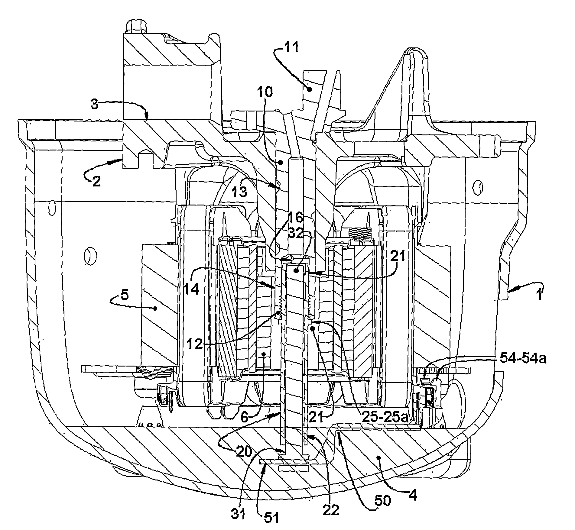
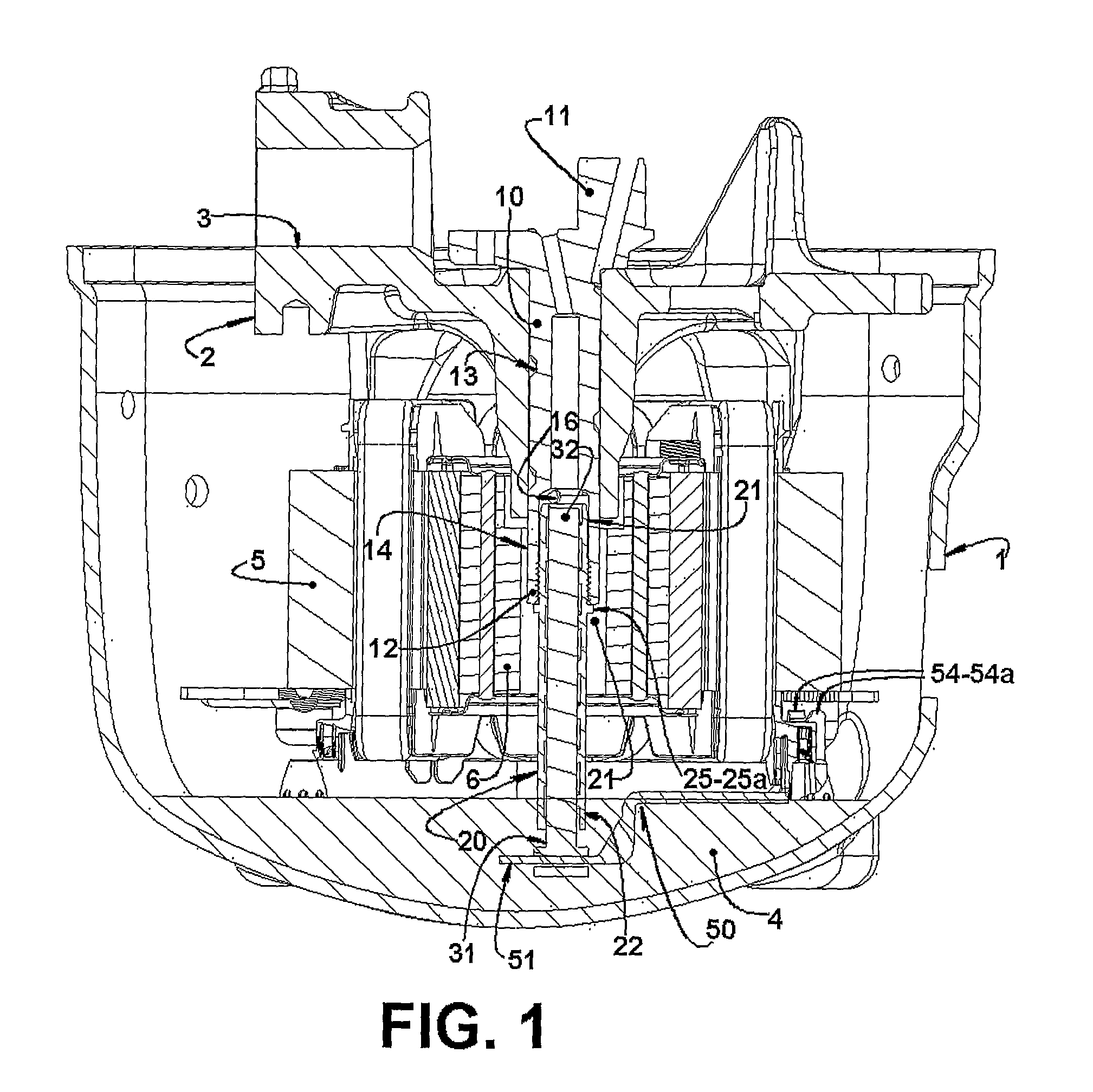
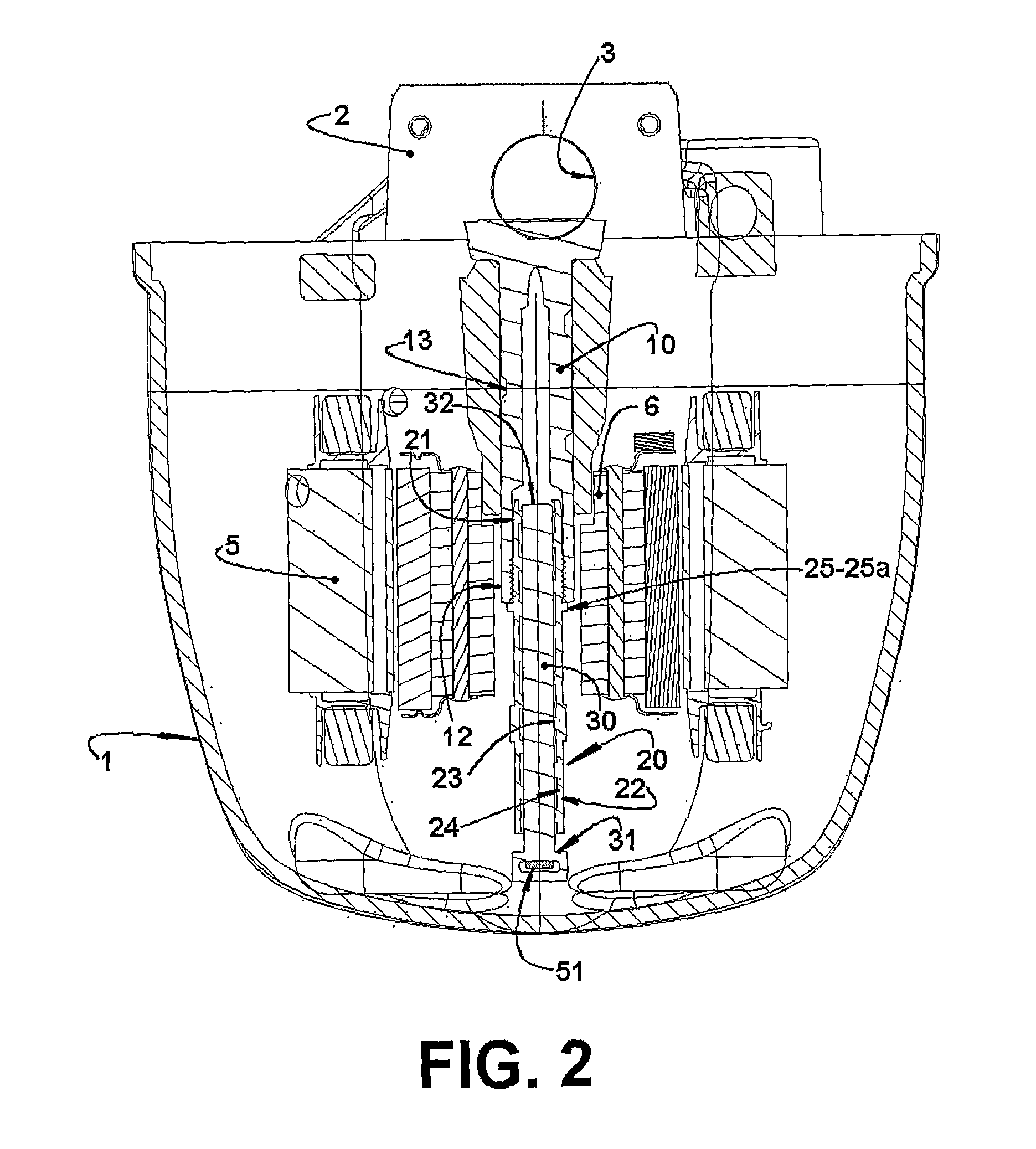
[0030]The present invention will be described for a reciprocating hermetic compressor (for example, of the type applied to a refrigerating system) presenting a generally hermetic shell 1, housing a cylinder block 2 which defines a cylinder 3 within which actuates a reciprocating piston (not illustrated), in a lower portion of the shell 1 being defined an oil reservoir 4, wherefrom the oil that lubricates the movable parts of the compressor is pumped through an oil pump.
[0031]In the present construction described herein, the refrigerating compressor is of the type which is driven by a crankshaft 10, which moves the piston, said crankshaft 10 superiorly presenting an eccentric portion 11 journalled to the cylinder block 2 and carrying, in a lower end 12, the oil pump of the present invention, which is operatively affixed to the rotor 6, so as to rotate therewith, and presents a lower portion immersed in the lubricant oil contained in the oil reservoir 4, and an upper portion which maintains fluid communication with a helical external oil channel 13 provided in the crankshaft 10 and which takes the oil pumped by the oil pump to the compressor parts to be lubricated.
[0032]The cylinder block 2 secures a stator 5 of an electric motor, further including a rotor 6 attached to the crankshaft 10, so as to rotate the latter upon operation of the motor.
[0033]According to the present invention, the oil pump comprises: a tubular sleeve 20, having an upper portion 21 affixed to at least one of the parts of crankshaft 10 and rotor 6, so as to rotate therewith, and a lower portion 22 having a lower end 22a immersed in the lubricant oil, said tubular sleeve 20 being provided with an inner surface 23 in which is provided, along at least part of its longitudinal extension, at least one helical groove 24 upwardly extending from the lower end 22a.
[0034]The oil pump of the present invention further comprises an elongated pump body 30 disposed in the interior of the tubular sleeve 20, so that an outer surface of the pump body 30 maintains a certain radial gap in relation to an adjacent confronting inner surface of the tubular sleeve 20, said pump body 30 having a lower end portion 31, projecting beyond the lower end 22a of the tubular sleeve 20, to be affixed to at least one of the parts of shell 1, cylinder block 2, and stator 5.
[0035]The tubular sleeve 20 is coupled to at least one of the parts of rotor 6 and crankshaft 10, so as to be rotatively driven with the part that carries it, upon rotation of the rotor 6, said movement being provoked by operation of the electric motor, whilst the pump body 30 remains rotatively fixed. The relative movement between the tubular sleeve 20 and the pump body 30 makes the oil flow upwardly from the oil reservoir 4, by mechanical dragging and centrifugal force.
[0036]In a way of carrying out the present invention, at least the tubular sleeve 20, in permanent contact with said crankshaft 10, is provided in plastic material.
[0037]In a particular constructive form, the tubular sleeve 20 and the pump body 30 are provided, for example, in plastic material.
[0038]The construction of the tubular sleeve 20 and pump body 30 in plastic material facilitates the manufacture of these components. Moreover, the manufacture in plastic material also minimizes the heat transfer from the crankshaft 10 to the oil being pumped, due to the low thermal conductivity of said material.
[0039]In one of the illustrated constructions (FIGS. 1-8 and 10-12), the tubular sleeve 20 and the pump body 30 present a constant circular cross-section along the respective longitudinal extension. However, it should be understood that other constructions are possible within the concept presented herein, such as a variable oblong cross-sectional construction for said parts of tubular sleeve and pump body.
[0040]In another way of carrying out the present invention illustrated in FIG. 9, the parts of tubular sleeve 20 and pump body 30 present a circular cross-section, but with a conical profile in their confronting surfaces. In this construction, the wall thickness of said tubular sleeve 20 ranges from a reduced thickness, adjacent to its lower end 22a, in which the inner diameter of said tubular sleeve 20 is the largest of this construction, to a greater wall thickness in the region of an upper end 21a of the upper portion 21 of the tubular sleeve 20, in which the inner diameter of said tubular sleeve 20 is the smallest of this construction. The variations of wall thickness and inner diameter of the tubular sleeve 20 are calculated so that they do not affect the pumping efficiency of the present oil pump.
[0041]The solution of a constant circular cross-section presents the advantage of presenting a better performance for the oil pumping, although presenting higher difficulty to obtain the components when these are made in plastic material. The construction in a conical profile has the advantage of more facility to obtain the component parts of the present oil pump when they are made in plastic material.
[0042]In a complementary form, the pump body 30 of the illustrated construction in FIG. 9 presents a conical profile having a larger diameter adjacent to its lower end 31, and a smaller diameter adjacent to its end 32, the diameter variation of said pump body 30 being gradual and continuous, as it occurs with the variation of the inner diameter of the tubular sleeve 20. It should be noted that the present solution further allows a stepped variation in at least one of the parts of inner diameter of the tubular sleeve 20 and outer diameter of the pump body 30, without impairing the pumping efficiency of the present pump.
[0043]According to the present invention, the tubular sleeve presents an inner surface wall 23, in which is provided, from the lower end 22a of said tubular sleeve 20, at least one helical groove 24 defining, with an adjacent confronting outer surface portion of the pump body 30, lubricant oil ascending channels C which conduct oil from the oil reservoir 4 and pumped by the present oil pump to the parts with relative movement of the compressor. The pump body 30 is mounted in the interior of the tubular sleeve 20, so as to be freely displaced in the interior of the latter, in radial directions orthogonal to the crankshaft 10 and rotatively fixed in relation to the rotor 6.
[0044]Since the helical groove 24 is provided in the inner wall of the tubular sleeve 20, the oil pump of the present invention presents an effect of centrifugal force and mechanical dragging superior to that of the prior art oil pump constructions.
[0045]In order not to alter the oil flow being upwardly drawn, the oil channels, defined by the helical grooves 24 produced in the inner surface 23 of the tubular sleeve 20, can be dimensioned so that the thickness thereof varies proportionally to the thickness variation of at least one of the parts of tubular sleeve 20 and pump body 30.
[0046]According to the present invention, the tubular sleeve 20 must be attached to at least one of the parts of rotor 6 and crankshaft 10, so as to be rotated by rotation of said rotor 6, directly by the movement thereof or by rotation of the crankshaft 10.
[0047]In a way of carrying out the present invention, such as illustrated in FIGS. 1-8, the tubular sleeve 20 is attached to the crankshaft 10, as described ahead, said crankshaft 10 presenting a tubular lower end portion 14, inside which is mounted the upper portion 21 of the tubular sleeve 20.
[0048]In the embodiment of the present invention illustrated in FIGS. 9-12, the tubular sleeve 20 is directly affixed to the rotor 6, although maintaining its upper portion 21 mounted in the interior of the tubular lower end portion 14 of the crankshaft 10.
[0049]While not illustrated, it should be understood that the present invention is not limited to a construction of crankshaft 10 internally mounting part of the tubular sleeve 20. The present solution is applied to constructions in which the tubular sleeve 20 may not be fitted in the interior of a tubular lower end portion 14 of the crankshaft 10. Besides, the present solution is also applied to constructions in which the crankshaft 10 externally affixes the tubular sleeve 20 of the oil pump, independent of the mounting arrangement of said tubular sleeve 20 in relation to the crankshaft 10.
[0050]In the constructions in which the crankshaft 10 does no present a tubular lower end portion 14, the tubular sleeve 20 can be mounted concentrical to the crankshaft 10, but externally thereto or also receiving, in an upper tubular portion defined in said tubular sleeve 20, an adjacent lower portion of said crankshaft 10.
[0051]Although the illustrated construction of tubular sleeve 20 and pump body 30 presents each of said parts formed in a single piece, it should be understood that both the tubular sleeve 20 and the pump body 30 can be provided by a plurality of pieces to be mounted to each other, each assembly of the plurality of pieces forming the desired length for the respective part of tubular sleeve 20 and of pump body 30.
[0052]According to a constructive form illustrated in FIGS. 1-8, the tubular sleeve 20 of the present oil pump externally carries, in its upper portion 21, a positioning stop 25, to be seated against an adjacent portion of the crankshaft 10, limiting the relative axial positioning between the tubular sleeve 20 and the tubular lower end portion 14 of the crankshaft 10. For this embodiment of the present invention, the positioning stop 25 limits the introduction of the upper portion 21 of the tubular sleeve 20 in the interior of the tubular lower end portion 14 of the crankshaft 10.
[0053]In this illustrated constructive option, the positioning stop 25 has the form of an annular peripheral flange 25a, externally provided in the upper portion 21 of the tubular sleeve 20, for example, incorporated in a single piece thereto.
[0054]In the illustrated construction, the peripheral flange 25a is seated against an adjacent stop face of the tubular lower end portion 14 of the crankshaft 10, in a condition in which the upper portion 21 of the tubular sleeve 20 is mounted in the interior of the tubular lower end portion 14 of the crankshaft 10. It should be understood that the condition in which the tubular sleeve 20 is mounted to the crankshaft 10 may be obtained by seating and affixing said peripheral flange 25a against an adjacent end face of the lower end 12 of the crankshaft 10, in the condition in which said tubular sleeve 20 is mounted to said crankshaft 10.
[0055]In a particular construction of the present invention, illustrated in the enclosed drawings, the peripheral flange 25a is annular and continuous, being provided around the whole periphery of the tubular sleeve 20. However, it should be understood that said peripheral flange 25a may be provided occupying only part of the peripheral extension of the tubular sleeve 20, or also provided in the form of flange segments around part or the whole of said peripheral extension of the tubular sleeve 20.
[0056]In another possible construction, the peripheral flange 25a is not incorporated to the tubular sleeve 20, and may be, for example, retained therein by an appropriate means, such as thread, fitting, glue, etc., permitting a desired adjustment for the introduction of the upper portion 21 inside the tubular lower end portion 14 of the crankshaft 10, particularly permitting the adjustment of the distance of the upper end 21a of said upper portion 21 of the tubular sleeve 20 in relation to an inner wall 14a of the tubular lower end portion 14 of the crankshaft 10 and which defines the innermost portion thereof.
[0057]The present oil pump further comprises retaining means 40, which affix the tubular sleeve 20 to at least one of the parts of rotor 6 and crankshaft 10, as described ahead.
[0058]For the construction illustrated in FIGS. 1-9, and in which the tubular sleeve 20 is attached to the crankshaft 10, the retaining means 40 comprise an inner thread 41, provided in an inner surface portion of the tubular lower end portion 14 of the crankshaft 10, to be engaged in an outer thread 42 provided in the upper portion 21 of the tubular sleeve 20, in an adjacent confronting portion of the outer surface of the latter, each of said inner thread 41 and outer thread 42 being defined along an extension of the respective surface in which it is provided.
[0059]It should be understood that the retaining means 40 may present other constructive forms for affixing the tubular sleeve 20 to the crankshaft 10, such as rivet, glue, mechanical interference, flexible fingers, external screwing, injection of the component in the shaft itself, etc., these constructive options not being limitative of the present invention.
[0060]In the constructive option illustrated in FIGS. 10-12, the tubular sleeve 20 is directly and concentrically attached to the rotor 6, through retaining means 40 provided in at least one of the parts of tubular sleeve 20 and rotor 6, so as to actuate in the other of said parts, affixing them to each other.
[0061]In a way of carrying out the present invention, the present oil pump comprises at least one retaining element 43, radially disposed and having an end 43a affixed in one of the parts of tubular sleeve 20 and rotor 6 and another end 43b affixed to the other of said parts.
[0062]In a particular form of this solution, at least one retaining element 43 has one of its ends incorporated, in a single piece, to the tubular sleeve 20, the other end being seated and affixed against an adjacent end face of the rotor 6, by at least one of the means defined by screws, glue, rivets, clamps, etc.
[0063]In the constructive form illustrated in FIGS. 10-12, the tubular sleeve 20 incorporates, in a single piece, from its upper portion 21, two pairs of retaining elements 43, in the form of radial projections disposed around the tubular sleeve 20 to prevent force resultants from acting thereon.
[0064]Each retaining element 43 has its other end 43b radially spaced from the surface of the tubular sleeve and seated against an adjacent end face of the rotor 6, in a condition in which the tubular sleeve is mounted to the latter, so as to allow the fixation of said tubular sleeve 20 to the rotor 6.
[0065]Each retaining element 43 is fixed to the rotor 6 by at least one of the means defined by screws, glue, rivets, clamps, mechanical interference, flexible fingers, etc.
[0066]In the construction illustrated in FIGS. 10-12, the retaining elements 40 are symmetrically distributed around the outer surface of the tubular sleeve 20, each presenting a respective retaining hole 44 provided in the other end 43b of each respective retaining element 43.
[0067]Upon mounting the tubular sleeve to the rotor 6 of this construction, each retaining element 42 is conducted to a mounting position to the rotor 6, so that each retaining hole 44 is aligned with a retaining channel 6a produced in the rotor 6, to allow the passage of a respective rivet or retaining screw 45, affixing the tubular sleeve 20 to the rotor 6.
[0068]In this construction, the retaining elements 42 define a stop means for introduction of the tubular sleeve 20 inside the tubular lower end portion 14 of the crankshaft 10.
[0069]The construction of retaining means 40 in the form illustrated in FIGS. 1-9, or in the form illustrated in FIGS. 10-12 of the enclosed drawings is defined as a function of the characteristics of the compressor in which the oil pump will be mounted. For compressors presenting a crankshaft 10 already provided with an inner thread portion defined in the tubular end portion 14 of said crankshaft 10, such as illustrated in FIGS. 1-9, (as it occurs in the compressors EG), the provision of the retaining means 40 in the form of helical thread is more appropriate. However, regarding the compressor constructions which do not present inner thread in the tubular end portion 14 of the crankshaft 10, as is the case of compressors EM, the retaining means 40 can present other constructions, such as that illustrated in FIGS. 10-12. It should be understood, however, that the constructions of retaining means 40 described and illustrated herein should not be considered as limitative of the concept of affixing the tubular sleeve 20 to at least one of the parts of crankshaft 10 and rotor 6.
[0070]In a constructive option in which the tubular sleeve is externally affixed to the crankshaft 10, the retaining means may also have the form of cooperating threads, one of which provided, for example, in the peripheral flange 25a and the other provided in the adjacent end portion 12 of the crankshaft 10. In another constructive form of retaining means within the concept presented herein, this can be defined by an annular flange mounted to the tubular sleeve 20 and to be seated against the rotor 6, or also in the form of a projection affixed to the rotor 6 and presenting an eye through which is fitted and affixed the tubular sleeve 20.
[0071]The mounting of the pump body 30 in the interior of the tubular sleeve 20 is carried out so that an upper end portion 32 of the pump body 30 is maintained with a certain axial spacing in relation to the interior of the tubular end portion 14 of the crankshaft 10, said axial spacing being particularly defined in relation to an adjacent inner wall portion 14a of the crankshaft 10. This axial spacing defines a passage chamber 16 in the interior of the crankshaft 10, to which is opened an upper end 24a of each helical groove 24 of each lubricant oil ascending channel C, permitting the fluid communication between the lubricant oil of the oil reservoir 4 and said passage chamber 16. In some constructions, the passage chamber is also defined in the interior of the tubular sleeve 20, adjacent to the upper end 21 of the latter. In a construction of the present invention, the passage chamber 16 maintains fluid communication with the oil outer channel 13 of the crankshaft 10, conducting lubricant oil to the compressor parts to be lubricated. In this construction, the crankshaft 10 defines an auxiliary reservoir in which is deposited the oil pumped from the oil reservoir 4, wherefrom it is pumped, through oil channels provided in the crankshaft 10, to the compressor parts away from the oil reservoir 4. In a particular variant of this construction, the oil reservoir is defined internal to the crankshaft 10.
[0072]In another embodiment of the present invention, the upper end 24a of each helical groove 24 is radially and directly open to the oil outer channel 13 of the crankshaft 10. In this case, the oil pumped from the oil reservoir 4 is directly conducted to the oil outer channel 13 of the crankshaft 10.
[0073]According to the present invention, the fixation of the pump body 30 to one of the parts of shell 1, cylinder block 2, and stator 5 is effected through a supporting means 50 having a first portion 51, which carries a lower end portion 31 of the pump body 30, and a second portion 52, through which the supporting means 50 is mounted to one of said parts of shell 1, cylinder block 2, and stator 5.
[0074]According to the present invention, the parts defined by the lower end portion 31 of the pump body 30 and by the first portion 51 of the supporting means 50 are loosely fitted to each other, so that the pump body 30 can be freely displaced in radial directions orthogonal to the crankshaft 10.
[0075]In the illustrated constructive form, the supporting means 50 comprises a rigid rod 50a having the first portion 51 loosely fitted in a radial housing 33 provided in the lower end portion 31 of the pump body 30, so as to support the latter.
[0076]In a way of carrying out the present invention, the rigid rod 50a is constructed in plastic material. The construction of the rigid rod 50a in plastic material facilitates the manufacture of this component. Furthermore, the construction in plastic material also minimizes heat transfer from the crankshaft 10 to the oil being pumped, as a function of the low thermal conductivity of said material.
[0077]According to the illustrated appended figures, the lower end portion 31 of the pump body 30 defines a widened base provided with the radial housing 33, which is in the form of a diametral through hole presenting an upper face 33a which seats onto the first portion 51 of the rigid rod 50a, and a lower face 33b, axially spaced from the first portion 51 of the rigid rod 50a by a value lower than that of the axial distance between the upper end portion 32 of the pump body 30 and the inner wall 14a of the tubular end portion 14 of the crankshaft 10, so as to prevent impacts between said parts, during operation or displacements of the compressor.
[0078]In the illustrated construction, the rigid rod 50a presents a double L-shaped profile, having two consecutive and continuous “L” portions, the two “L” portions of said rigid rod 50a being, in the illustrated construction, interconnected with at least one structural rib 53 between a base portion of one of the “L” portions and an adjacent elevated portion of another of said “L” portions.
[0079]It should be understood that the provision of the structural rib 53, which is a particular illustrated construction, should not be limitative. In another embodiment of the present invention, the “L” portions are provided in a single piece formed in a sufficiently resistant material, so as not to require the provision of a structural rib.
[0080]According to the present invention, one of the “L” portions presents its respective elevated portion affixed to one of the parts of shell 1, cylinder block 2 and stator 5 and, the other “L” portion presents its respective base portion fitted in the radial slot 33 of the pump body 30. In the illustrated construction, a first “L” portion has its respective base portion fitted in the radial slot 33 of the pump body 30 and is disposed inferiorly to a second “L” portion, which is provided, in its respective elevated portion, with fixation means 54, for example, in the form of fingers 54a which are elastically deformed to be affixed to the stator 5, particularly to a stator cover 60 of known construction and usually mounted in a lower end of the stator, turned to the oil reservoir 4.
[0081]According to the present invention, while a particular construction of fixation rod 50a has been described, it should be understood that the rod can present any profile which guarantees the desired rigidity, its fixation to the stator 5 being carried out by other fixation means 54 besides that illustrated in the form of fingers 54a, said fixation means 54 being, for example, glue, screw, rivet, clamps, quick fitting (“snap-on”), welding, etc.
[0082]Although the concept presented herein has been described mainly considering the oil pump construction illustrated, it should be understood that this particular construction does not restrict the applicability or scope of the present invention. The intention is to protect the principle and not the specific application or constructive form.
[0083]It should be understood that for any of the possible options for constructing and mounting the tubular sleeve 20 to the rotor and/or to the crankshaft 10 (internal or external to this), as well as the provision and construction of the retaining means 40, the oil pump of the present invention presents its pump body affixed to one of the parts of shell 1, cylinder block 2 and stator 3 with a supporting means, as cited above and which, for example, presents the construction described and illustrated herein, but which should not be considered as limitative of the presented concept.

PUM

no PUM

Description & Claims & Application Information

We can also present the details of the Description, Claims and Application information to help users get a comprehensive understanding of the technical details of the patent, such as background art, summary of invention, brief description of drawings, description of embodiments, and other original content. On the other hand, users can also determine the specific scope of protection of the technology through the list of claims; as well as understand the changes in the life cycle of the technology with the presentation of the patent timeline. Login to view more.
Why Eureka
Try Eureka