
System and Method for Enabling Coordinated Beam Switching and Scheduling

a beam switching and scheduling technology, applied in the field of wireless communication, can solve problems such as interference increase and change in channel quality, and achieve the effects of reducing computational overhead, reducing communications overhead, and reducing computational overhead

Active Publication Date: 2010-03-25
FUTUREWEI TECH INC
View PDF19 Cites 132 Cited by
  • Summary
  • Abstract
  • Description
  • Claims
  • Application Information

AI Technical Summary

Benefits of technology

The patent describes a system and method for dynamically assigning persistent resources in a wireless communications system. This helps to improve the efficiency of the system by optimizing resource allocation. The system includes multiple controllers and communications devices, and each controller transmits a unique beam formed reference signal (BFRS) to measure the communications channel between the controller and the communications devices it serves. The BFRS is beam formed using a plurality of beam patterns, and a beam pattern changes once per transmission unit. This eliminates the need for the user equipment (UE) to perform channel estimation and report channel estimates of interfering cells to the serving network, reducing computational and communications overhead. The system also provides a complete picture of the interference environment of the UEs, regardless of the configuration of neighboring network units. Overall, the technical effects of the patent include improved efficiency, reduced computational and communications overhead, and improved interference management.

Problems solved by technology

However, one main drawback of beamforming is the so called flashlight effect where the channel quality changes between user equipment (UE) measurement and reporting, and NodeB (NB) transmission, due to the changes in the beam pattern of the interfering neighbouring cells.
It is well known that as cell size is decreased in an effort to improve spectral efficiency, interference increases.

Method used


Image

  • System and Method for Enabling Coordinated Beam Switching and Scheduling
  • System and Method for Enabling Coordinated Beam Switching and Scheduling
  • System and Method for Enabling Coordinated Beam Switching and Scheduling

Examples


Embodiment Construction

[0029]The making and using of the embodiments are discussed in detail below. It should be appreciated, however, that the present invention provides many applicable inventive concepts that can be embodied in a wide variety of specific contexts. The specific embodiments discussed are merely illustrative of specific ways to make and use the invention, and do not limit the scope of the invention.

[0030]The embodiments will be described in a specific context, namely a wireless communications system with NodeBs (NB) using beamforming to transmit to User Equipment (UE) using directional beam patterns, where the transmissions of the NBs may be synchronized with one another. The invention may be applied to wireless communications systems using a wide range of wireless access technologies, such as LTE, LTE-Advanced, and so forth. Additionally, the invention may also be applied to NBs using non-directional beam patterns.

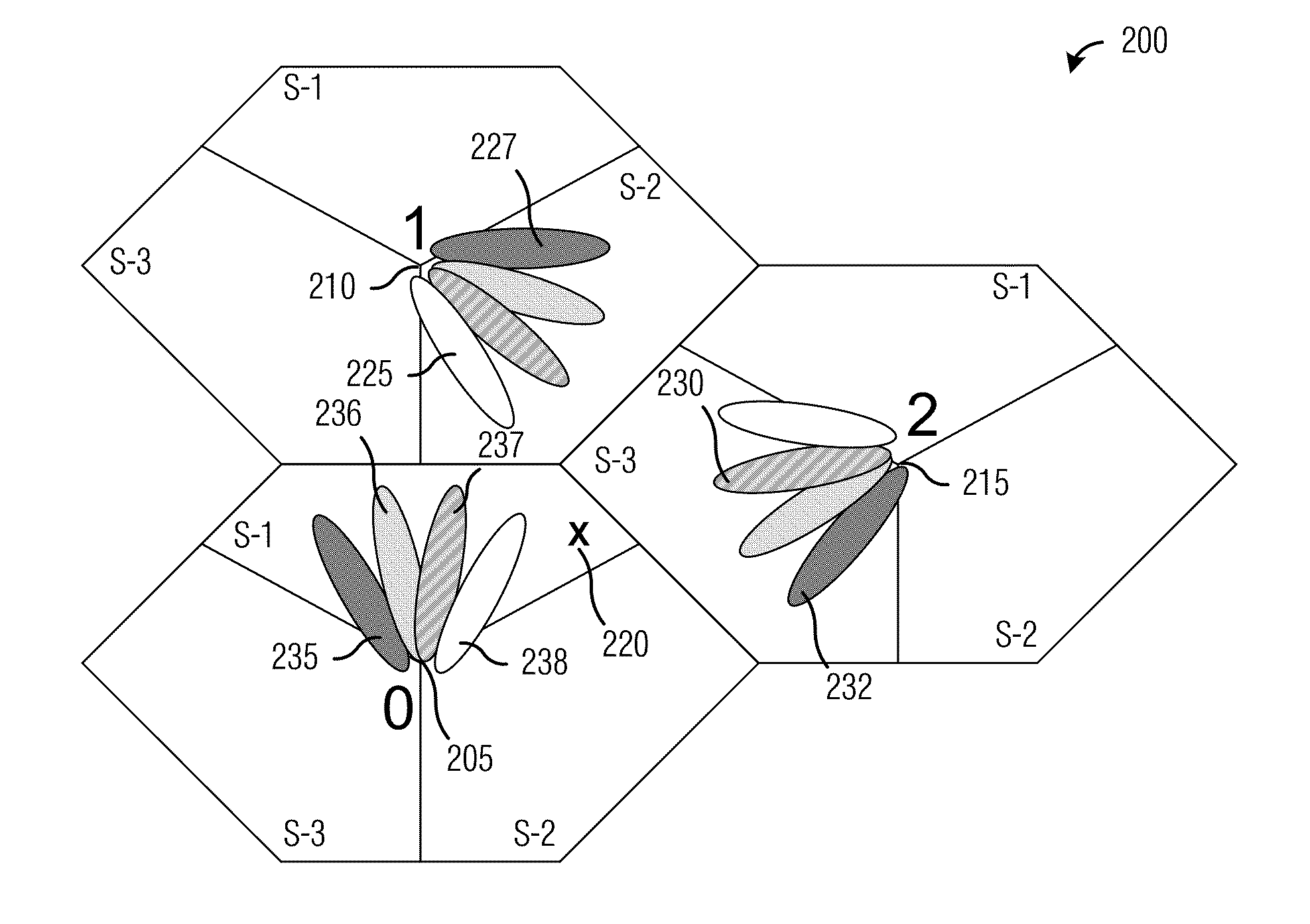
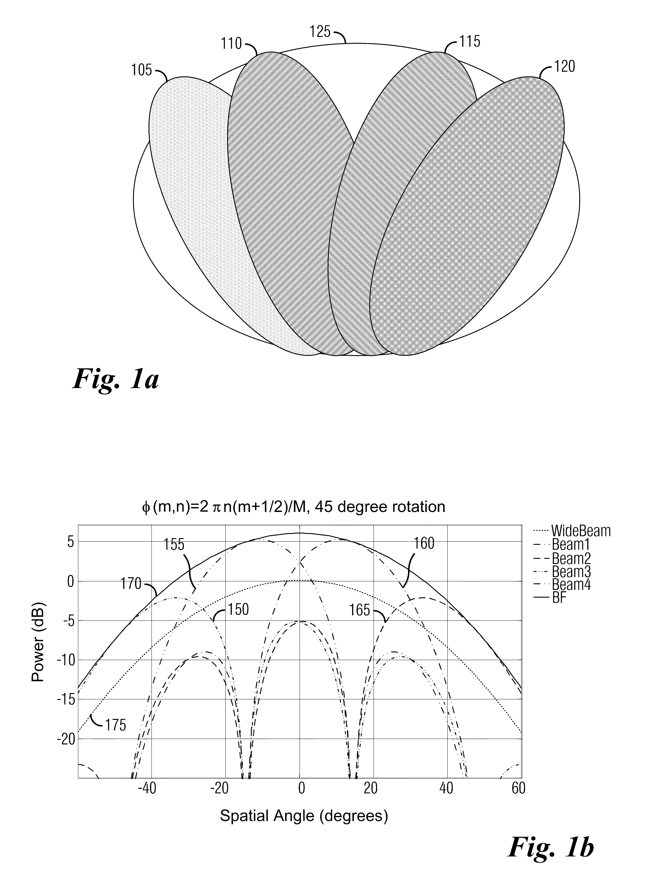
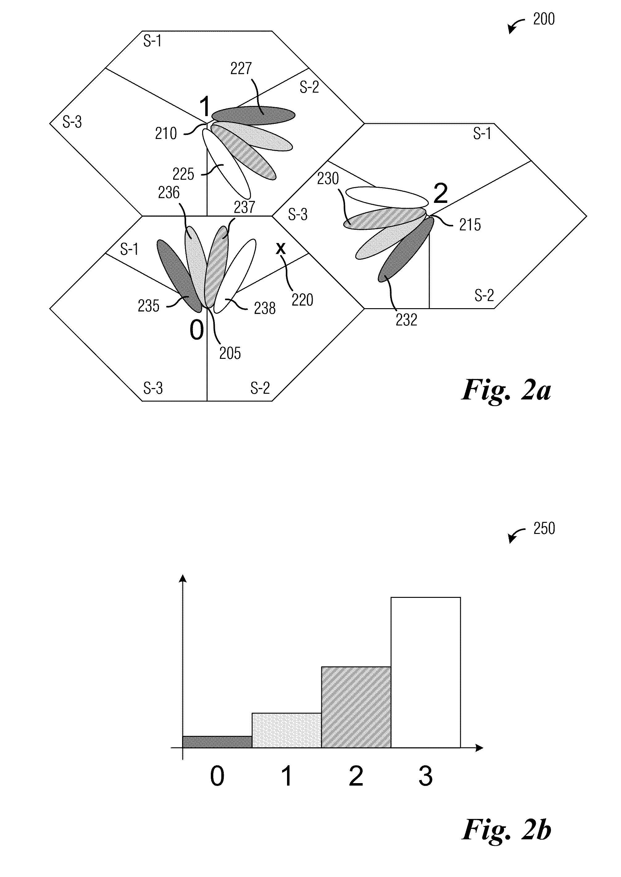
[0031]FIG. 1a illustrates possible antenna beams from a plurality of antenn...


PUM


Abstract

A system and method for enabling coordinated beam switching and scheduling in a wireless communications system. A method for controller operation includes indicating that the controller is operating in a cooperative beam switching mode, transmitting a beam formed reference signal (BFRS), from each communications device being served by the controller, receiving a measurement of a communications channel between the controller and the communications device and an indicator indicating a transmission unit corresponding to the measurement of the communications channel, receiving a transmission intended for a communications device, and causing the transmission to be transmitted to the communications device. The BFRS is beam formed using a plurality of beam patterns, the beam pattern used in beam forming the BFRS changes once per transmission unit, and the transmission is transmitted using measurement of the communications channel and the indicator from the communications device.

Description

[0001]This application claims the benefit of U.S. Provisional Application No. 61 / 099,094, filed on Sep. 22, 2008, entitled “Signaling Method to Enable Coordinated Beam Switching and Scheduling in an LTE Cellular System,” which application is hereby incorporated herein by reference.CROSS-REFERENCE TO RELATED APPLICATIONS[0002]This application is related to the following co-assigned patent applications: Ser. No. 12 / 412,624, filed Mar. 27, 2009, entitled “System and Method for Wireless Communications;” Ser. No. 61 / 172,622, filed Apr. 24, 2009, entitled “System and Method for Allocating Beams in Time-Frequency Space Enabled Coordinate Beam Switching in a Wireless Communications System;” Ser. No. 61 / 173,404, filed Apr. 28, 2009, entitled “System and Method for Coordinating Electronic Devices in a Wireless Communications System;” and Ser. No. 12 / 534,271, filed Aug. 3, 2009, entitled “System and Method for Synchronized and Coordinated Beam Switching and Scheduling in a Wireless Communicati...

Claims


Application Information

Patent Timeline
Patent Type & Authority Applications(United States)
IPC IPC(8): H04B7/00H04B17/00
CPCH04B7/024H04B7/0632H04B7/0617
Inventor VAN RENSBURG, CORNELIUSHOSEIN, PATRICK AHAMADSOONG, ANTHONY C.K.
Owner FUTUREWEI TECH INC
Learn More