Vane-type camshaft adjuster

Inactive Publication Date: 2010-03-25
HYDRAULIK RING
View PDF3 Cites 18 Cited by
  • Summary
  • Abstract
  • Description
  • Claims
  • Application Information

AI Technical Summary

Benefits of technology

[0007]According to an advantage of the invention, a vane-type camshaft adjuster is being utilized. The vane-type camshaft adjuster is dimensioned in an axially very short manner, which benefits the tight installation space of drive trains installed both in transverse and longitudinal directions.
[0008]According to another advantage of the invention, a coil spring having a rectangular profile supports the rotor opposite of the stator at a certain angular position. In case of the camshaft being associated with the exhaust, the rotor may be brought into an early exhaust camshaft position required for starting the motor by means of the coil spring. In general the alternating torques of the camshaft may be compensated in both camshafts—i.e. intake and exhaust—by means of prestressing the coil spring, which have an effect, the strength of which varies in both torque devices of the camshaft. The alternating torques are created by means of the valve spring forces applied to the gas shuttle valves, and strongly depend on the number of cylinders. The alternating torques become increasingly inhomogeneous, the fewer cylinders are present in the internal combustion engine. For this purpose the coil spring may be rotated “early” into the torque direction in idle position in a particularly advantageous manner, since the adjustment of the vane-type camshaft adjuster in the torque device setting “late” already occurs quicker due to the supporting effect by means of the alternating torques. In this manner the adjustment to “early” is carried out just as quickly as in “late” by means of the coil spring.
[0009]A coil spring having a rectangular profile may be produced having particularly low tolerances. In this manner the rectangular wire of the coil spring may be gripped particularly well by a clamping device, and subsequently bent. In this case the bent angular area enables the coil spring to be further held in the bent angular area by a clamping device, and to wind the coil to an exact measure. For example, a round wire would be difficult to grip using a clamping device in this case, since such a round wire can be gripped only in a negative fitting and not in a positive fitting manner. For this purpose the winding is accomplished essentially about the center

Problems solved by technology

For example, a round wire would be difficult to grip using a clamping device in this case, since such a round wire can be gripped only in a negative fitting and not in a positive fitting manner.
For this purpose, however, the coil spring

Method used


Image

  • Vane-type camshaft adjuster
  • Vane-type camshaft adjuster
  • Vane-type camshaft adjuster

Examples


Example

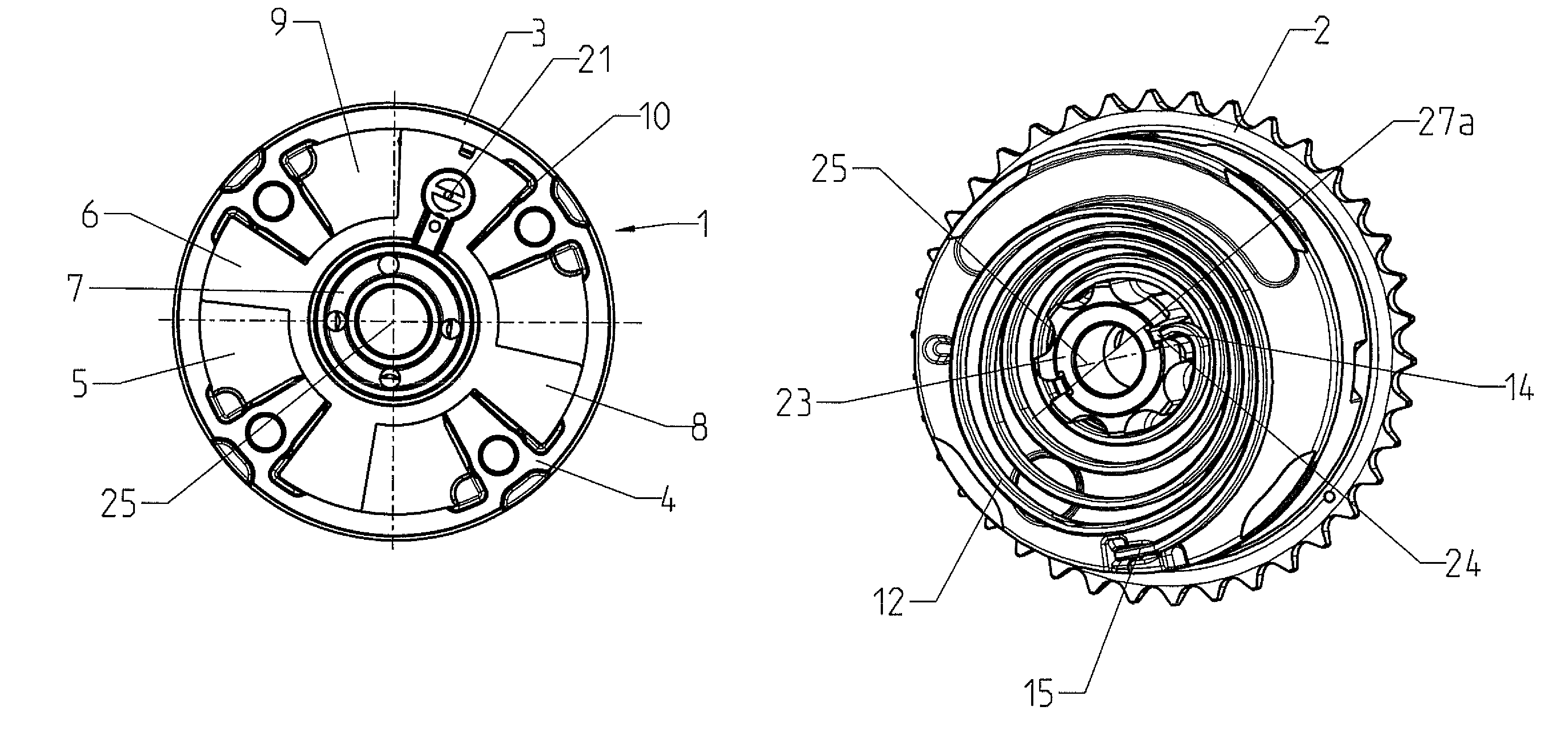
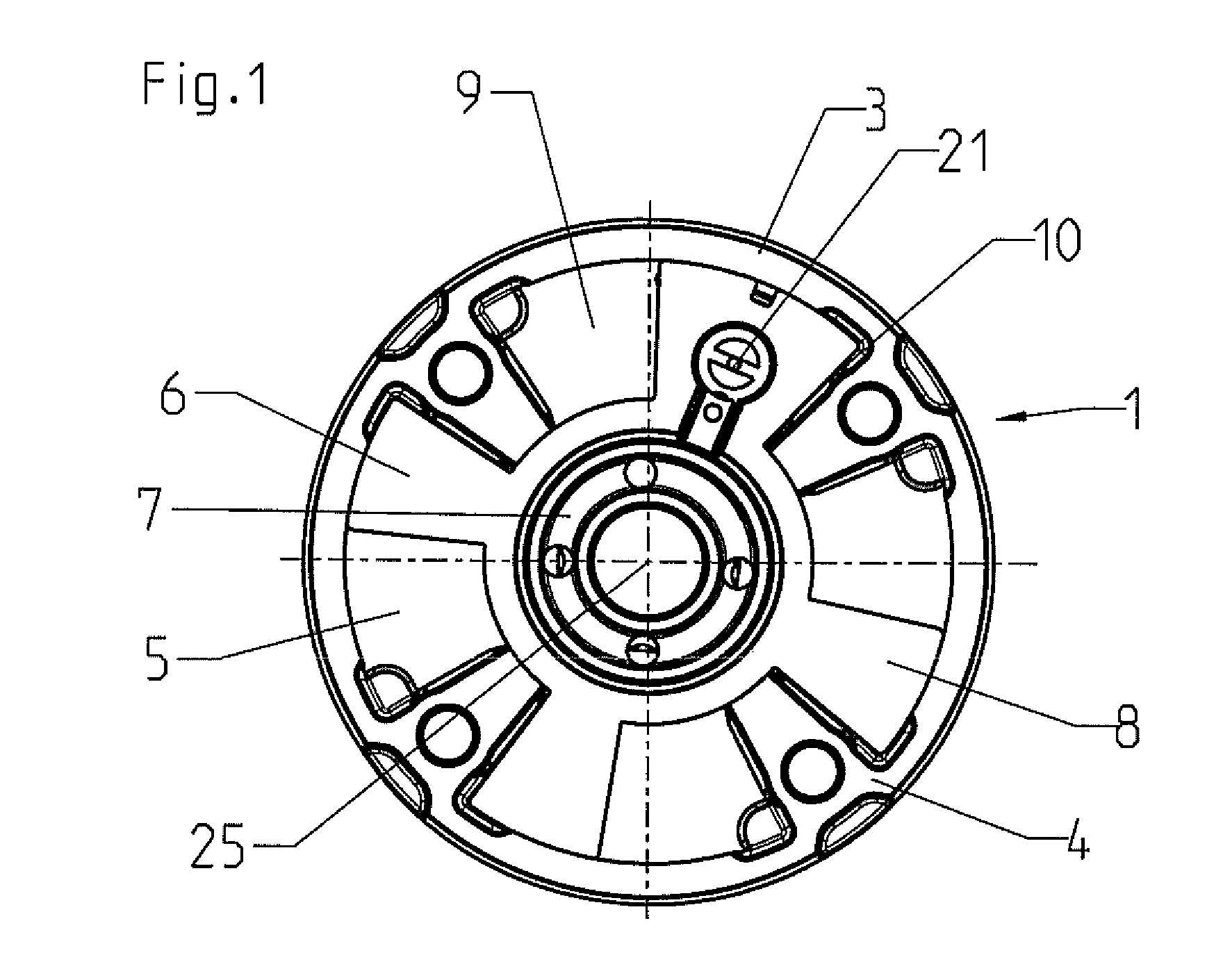
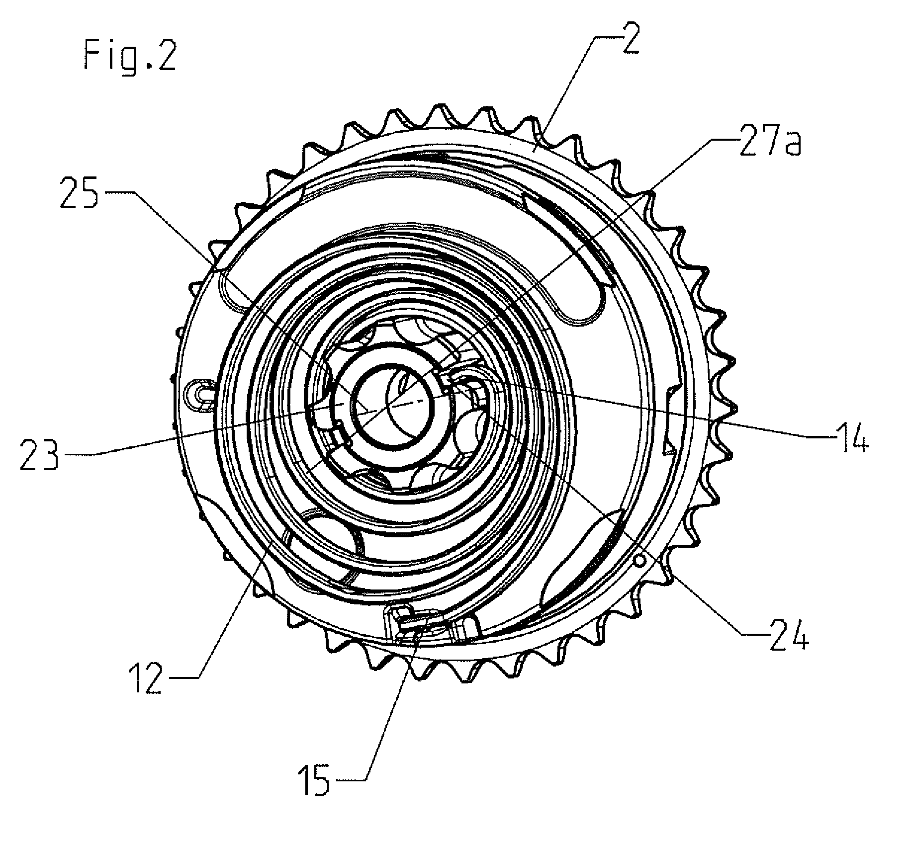
[0021]The angular position between the crankshaft and the camshaft is modified using a vane-type camshaft adjuster during the operation of an internal combustion engine. By pivoting the camshaft the opening and closing times of the gas shuttle valves are displaced such that the internal combustion engine delivers its optimum power at the respective rotational speed. The vane-type camshaft adjuster enables an infinitely variable adjustment of the camshaft relative to the crankshaft. The vane-type camshaft adjuster has a cylindrical stator 1 that is connected to a gearwheel 2 illustrated in FIG. 2 in a pivot-proof manner. In the exemplary embodiment the gearwheel 2 is a chain wheel, via which a chain (not illustrated in detail) is guided. However, the gearwheel 2 may also be a toothed belt wheel, via which a drive belt is guided as the drive element. The stator 1 is drive-connected to the crankshaft via the drive element and the gearwheel 2 in a commonly known manner.

[0022]As an alter...


PUM


Abstract

A vane-type camshaft adjuster has a side plane that is arranged perpendicular to the center axis of the camshaft adjuster. A coil spring abuts the side plane and is connected between a rotor and stator to maintain the rotor at a certain angular position relative to the stator.
In order to create a vane-type camshaft adjuster, the righting moments of which are adjusted in a particularly accurate manner, the coil spring has a rectangular profile, wherein a spring section is angled through the side plane such that the coil spring is supported relative to the stator or the rotor in a pivot-proof positive fitting manner.

Description

CROSS-REFERENCE TO RELATED APPLICATIONS[0001]This application claims priority under 35 U.S.C. §119 to German App. No. 10 2008 048 386.9, filed Sep. 22, 2008, and which is incorporated herein by reference.BACKGROUND[0002]The invention relates to a vane-type camshaft adjuster according to the generic part of patent claim 1.[0003]A vane-type camshaft adjuster is already known from U.S. Pat. No. 7,004,129 B2. A coil spring is seated on a side plane of a stator that is arranged perpendicular to the center axis thereof. The coil spring strives to maintain a rotor at a certain angular position against the stator. The coil spring comprises a wire having a round profile. The wire is supported on the stator on the outer end opposite of protrusions by means of a first bend. The coil spring is supported opposite of the rotor on the inner end by means of a second bend.[0004]A camshaft adjusting device of a different type is known from EP 0 356 018 A1, wherein a coil spring having a rectangular p...

Claims


Application Information

Patent Timeline
IPC IPC(8): F16D3/10
CPCF01L1/3442F01L2001/34483F01L2001/34426F01L1/04F01L1/34F02D13/02
Inventor ISENBERG, KARL HEINZDOGAN, FATIH
Owner HYDRAULIK RING
Why Eureka
Try Eureka