Microtitration plate

Inactive Publication Date: 2005-03-17
EPPENDORF AG
15 Cites 28 Cited by

AI-Extracted Technical Summary

Problems solved by technology

The plastic concerned may be polycarbonate which ...

Benefits of technology

[0022] For manufacture at particularly low tolerances, it is preferred to mold the frame initially and the vessels subsequently. This has the advantage that the frame first may undergo a certain shrinkage before the vessels are molded thereto. The time interval from molding the frame to molding the vessels thereto may be chosen so that the shrinkage of the frame (by cooling it down) essentially is effected completely. Once the vessels are molded on, shrinking techniques virtually do not impair the ...

Abstract

A microtitration plate has a frame (2) made of a first stiff plastic and having a plate (4) with multiplicity of holes (2′), and a multiplicity of vessels (3) made of a second plastic suited for the PCR and/or exhibiting permeability to oxygen, which are fixedly connected to the plate (4) by directly molding them to the holes (6), which have a receiving portion (9, 10, 11) protruding from an underside (8) of the plate (4), and which are accessible from an upper surface (7) of the plate through apertures (15).

Application Domain

Technology Topic

Image

  • Microtitration plate
  • Microtitration plate
  • Microtitration plate

Examples

  • Experimental program(1)

Example

[0041] In the drawings, the same elements are designated by identical reference numerals. The description pertaining thereto applies to all of the embodiments.
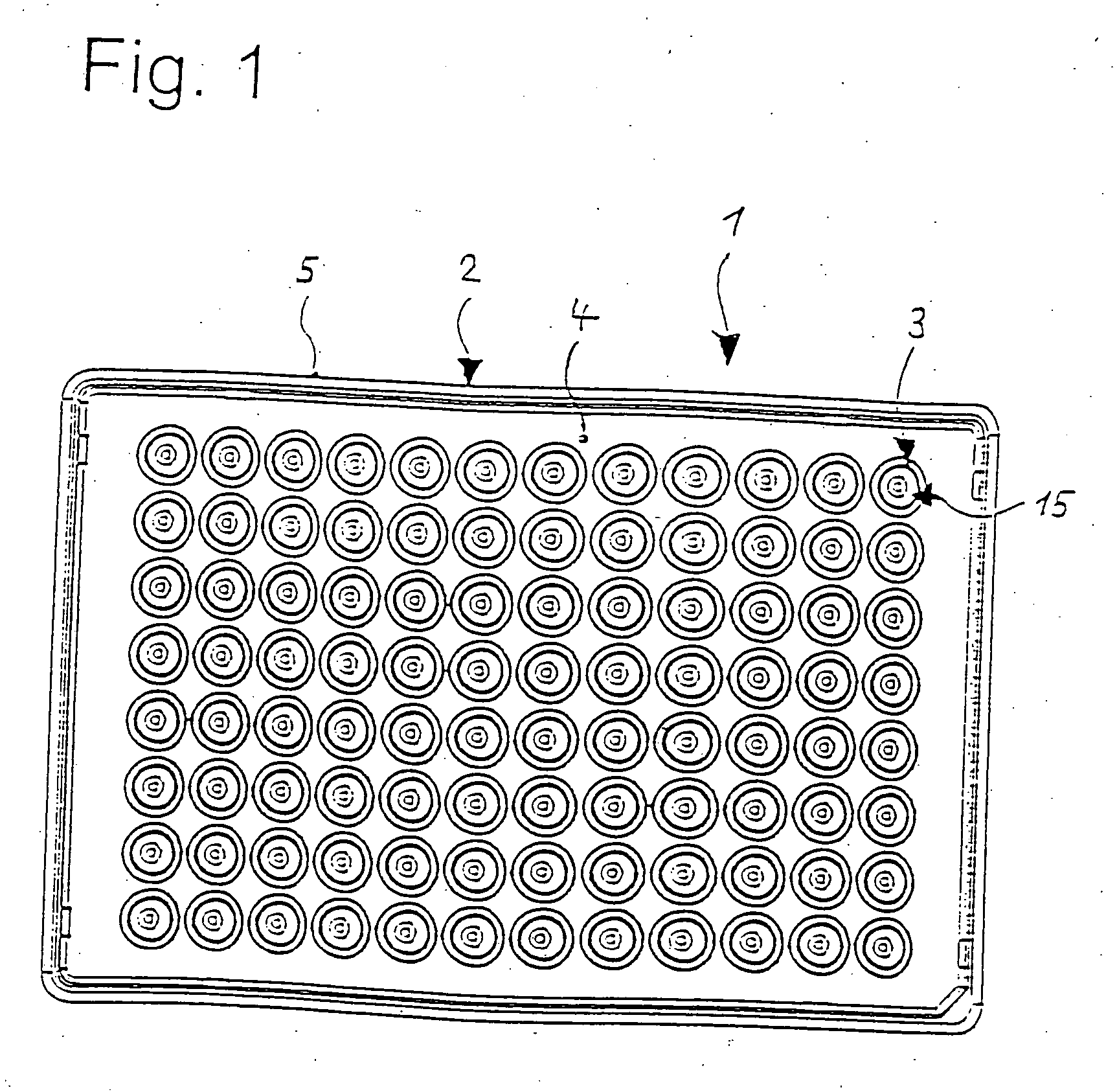
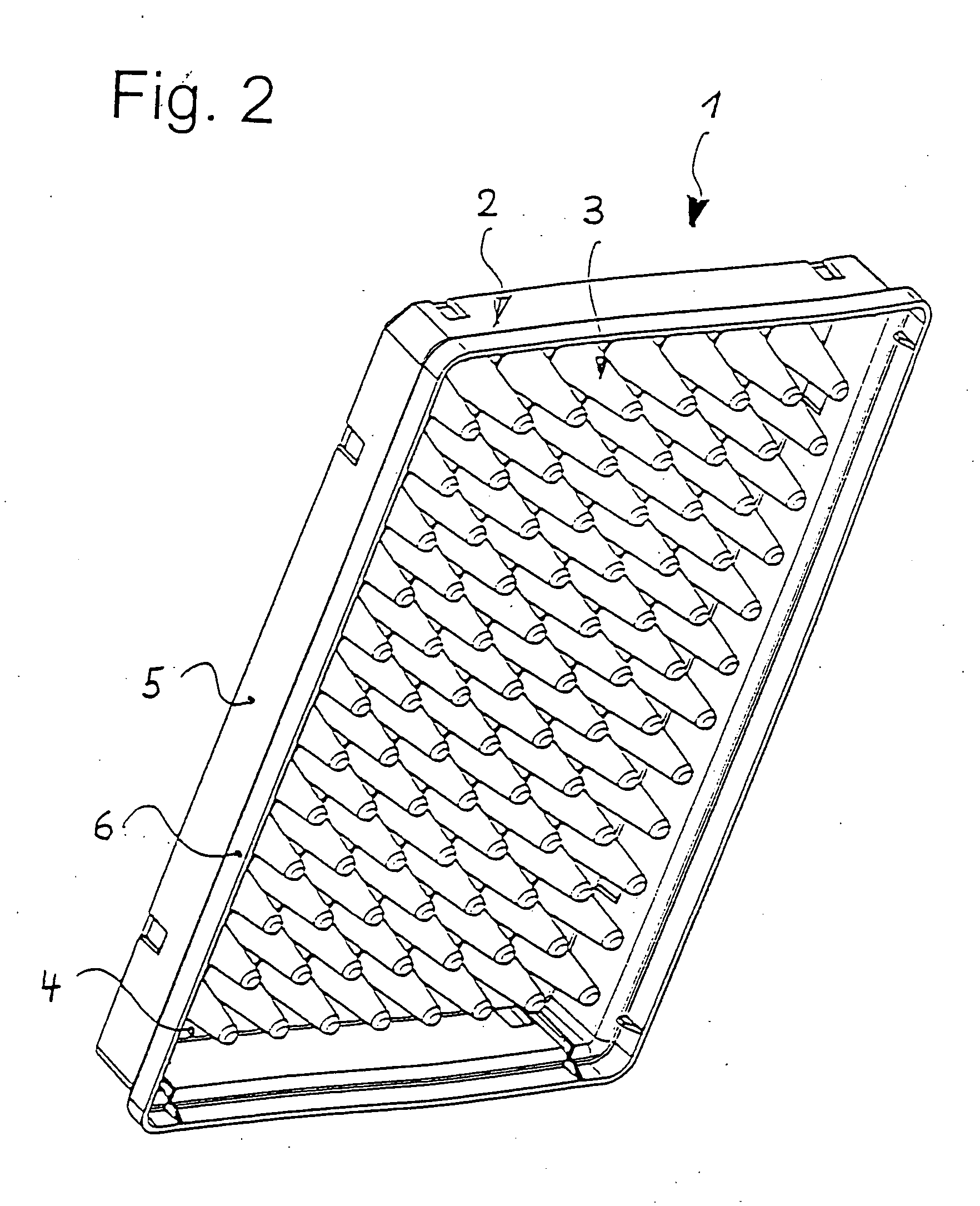
[0042] Referring to FIGS. 1 through 3, a microtitration plate 1 comprises a frame 2 and a multiplicity of vessels 3. There is a total of 96 vessels arranged in eight columns and twelve rows.
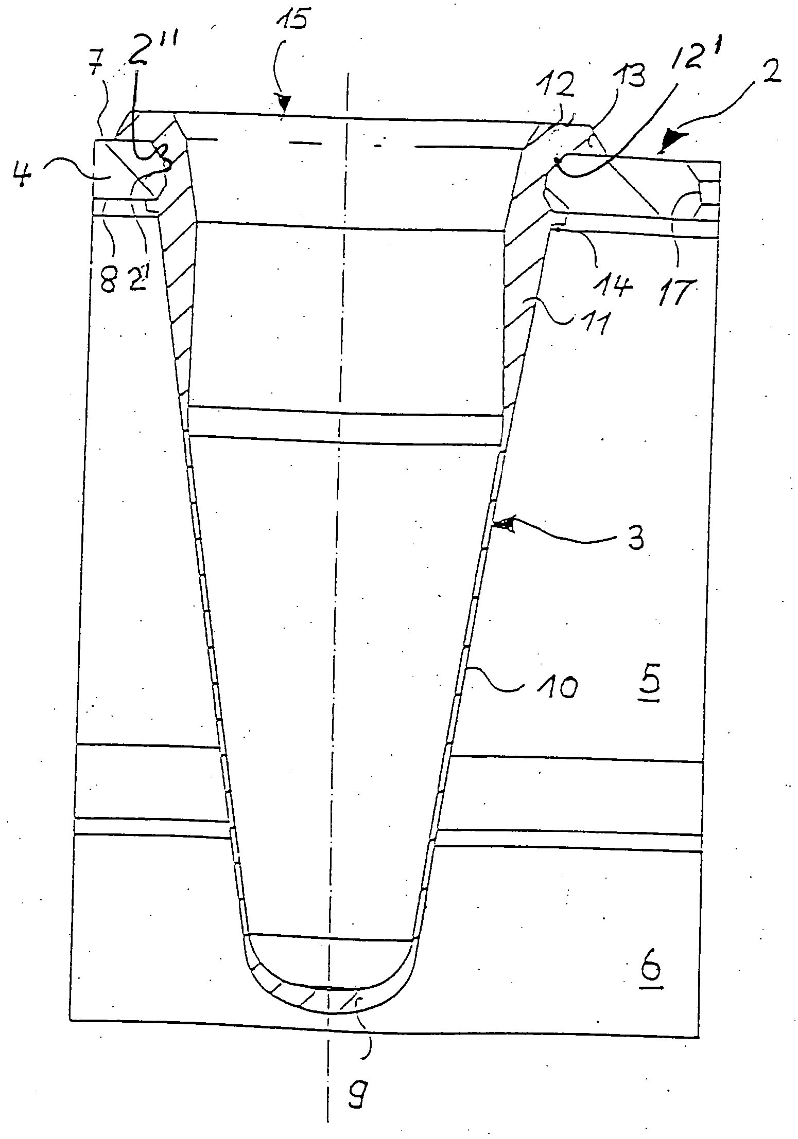
[0043] The frame 2 has a substantially rectangular plate 4 the outer edge of which is surrounded by a bordering 5 which protrudes approximately perpendicular from the underside of the plate 4, i.e. beyond the vessels 3. At bottom, the bordering 5, as is known, has an expansion 6 which enables stacking on the upper surface of an appropriate microtitration plate 1.
[0044] The frame 2 has a total of ninety-six holes 2′ in the plate 4. These have a profile 2″ of the cross-section which widens towards the upper surface 7 of the plate 4 in two portions of different conicity and towards the underside 8 of the plate 4 in a conical portion.
[0045] In a first molding step, the frame 2 is integrally molded from a plastic which is relatively rigid when cured. Gate marks are formed at the edge of frame 2, e.g. at the lower edge of the bordering 5.
[0046] At their base, vessels 3 have a cup-shaped bottom 9 which is bordered by a conical wall portion 10 of a very small wall thickness (about 0.1 mm). Above it, there is a wall portion 11 the wall thickness of which gradually increases towards the top. At its outside, it has the same conicity as the wall portion 10. At its inside, however, it is designed nearly cylindrically, which results in an approximately wedge-shaped profile of the cross-section.
[0047] Wall portion 11 terminates in a collar 12 which also is of a largely increased wall thickness with respect to wall portion 10. Vessels 3 are molded to plate 4 in the area of collar 12. To this end, a collar 12 externally bears against the inner periphery of holes 2′. It further has a projection 13, 14 at the upper surface 7 and the underside 8 of plate 4, respectively. With the engagement of the projections 13, 14 with the upper surface 7 and the underside 8, a formlocking connection of the collar 12 and, thereby, of the vessel 3 with plate 4 is formed.
[0048] As shown in FIG. 3, the collar 12 has an outer profile 12′ of the cross-section that widens likewise as the profile 2″ of the hold 1′, toward the upper surface 7 of the plate 4 in two portions of different conicity and toward the underside 8 of the plate 4 in a conical portion, i.e., the cross-sectional profile 2″ of the hole 2′ and the cross-sectional profile 12′ of the collar 12 are complementarily formed. Therefore, a form locking connection is already formed when a vessel 3 is inserted in the hole 2′. The projections 13, 14 only inhance the already formed form locking connection. The collar 12 can have not two but only one projection 13 or 14. Both projections are necessary when the complementary profiles of the vessel 3 and the hole 2′ have a circular cross-section.
[0049] Though a specific cross-sectional profile of the hole 2′ and the vessel 3 was described, it should be understood that they can have a different shape, e.g. the hole wall can have a convex profile, with the outer surface of the collar having a concave profile. Further, the complementary profiles of the hole 2′ and the vessel 3 can be formed of two sections, a cylindrical section and a conical section widening to the upper surface 7 of the plate 4 or to the underside 8. In case the conical section widens toward the upper surface 7 of the plate 4, the collar 12 is provided with a bottom projection 14. If the comical section widens to the underside 8 of the plate 4, the collar is provided with the upper projection 13.
[0050] In the area of collar 12, vessels 3 have a cross-section expanding towards the top in two portions of different conicity. Vessels are accessible from the upper surface of plate 4 through apertures 15.
[0051] All of the vessels are simultaneously molded directly to the frame 2 and the holes 2′ thereof. Each vessel 3 has its own central gate mark at the underside of bottom 9. This helps achieve shorter flow paths of the plastic which are made possible by the particularly small wall thickness in wall portion 10. The material used is polypropylen or LSR, for example, for the purpose of the PCR or oxygen supply to a sample inside the vessel.
[0052]FIG. 4 shows a microtitration plate 1′ in which the frame 2″ and the vessels 3′ are integrally made of a single plastic in a known manner. The outer shape of microtitration plate 1′ substantially corresponds to that of the preceding example with the vessels 3′, however, having a substantially uniform course of wall thickness and are fused to plate 4′ with no projections. At the edge, plate 4′ is connected, in a known manner, to bordering 5′ which has the expansion 6′ at the bottom.
[0053] Vessels 3′ are accessible from the top through apertures 15′ with an annular sealing 16 made of an elastic material being disposed around each aperture. In the example, it is a plastic which is capable of getting connected to the plastic of microtitration plate 1′ by being bonded thereto.
[0054] Instead, a non-positive connection may be produced by placing seal 16 in an undercut groove in the upper surface of plate 4′.
[0055] Preferably, seals 16 are fixedly connected to microtitration plate 1′ by a multicomponent molding technique.
[0056] Now, it is possible to sealingly close apertures 15′ by placing thereon a lid (not shown) made of a rigid material. The lid may approximately have the dimensions of plate 4′. Preferably, it is locked in the marginal area of microtitration plate 1′. Such locking may be effected, for example, in the recesses 17 which the bordering 5′ has directly beneath plate 4′.
[0057] The embodiment of FIG. 5 differs from the aforementioned in that the adjoining annular seals 16 are connected to each other by straight-lined webs 18, 19 which extend in the row and column directions. This may be advantageous particularly for technical reasons of manufacture, but also for reasons of fixedly connecting the seals to the microtitration plate 1′ or for providing additional sealing.
[0058] Referring to FIG. 6, a microtitration plate 1′ is shown which is made of a single material only in correspondence to the one of FIG. 4. However, there are no annular seals 16 here. Plate 4′ of microtitration plate 1′ has seated thereon a lid 20. It has a plate 21 the contours of which substantially are the same as those of the plate 4′. Plate 21 is supported on the upper surface of plate 4′ in marginal areas 21′. It is spaced by a small gap from plate 4′ in a region 21″ between marginal areas 21′. This allows it to be placed onto conventional microtitration plates which have sealing collars at the upper surface of retaining plate 4′.
[0059] In region 21″, plate 21 has plug-like seals 22 which protrude from its underside. These plug-like seals 22 have a circumferential sealing bulge 23 at their outer periphery.
[0060] Each aperture 15′ of vessels 3′ has associated thereto a seal 22. Here, seals 22 engage apertures 15′ so as to sealingly cause their sealing bulges 23 to bear against the inner wall of vessels 3′.
[0061] Seals 22 are disposed in appropriate recesses of plate 21. They are connected to each other by short webs 24, 25 which extend in the row and column directions.
[0062] Borderings 26 protrude from the underside of the plate at the edge thereof, from which borderings catch projections 27 protrude inwardly which are adapted to be locked in the recesses 17 (see FIG. 4) of microtitration plate 1′. Handles 28 project upwardly from borderings 26. Those make it easier for lid 20 to be locked. Furthermore, pivoting the handles 28 makes it possible to disconnect the locking engagement between catch projections 27 and recesses 17 because the borderings 26 will be pivoted along.
[0063] Preferably, lid 21 with seals 22 is also manufactured by a multi-component molding technique.

PUM

PropertyMeasurementUnit
Thickness5.0E-5 ~ 2.5E-4m
Softness
tensileMPa
Particle sizePa
strength10

Description & Claims & Application Information

We can also present the details of the Description, Claims and Application information to help users get a comprehensive understanding of the technical details of the patent, such as background art, summary of invention, brief description of drawings, description of embodiments, and other original content. On the other hand, users can also determine the specific scope of protection of the technology through the list of claims; as well as understand the changes in the life cycle of the technology with the presentation of the patent timeline. Login to view more.

Similar technology patents

Printing cartridge having self-referencing printhead

ActiveUS20070126826A1Eliminate effectsLow tolerancePrintingIntegrated circuitNozzle
Owner:MEMJET TECH LTD +1

Access port

Owner:B BRAUN MEDICAL

Classification and recommendation of technical efficacy words

  • Increase wall thickness
  • Low tolerance

Microcircuits for small engines

ActiveUS20070177976A1Increase wall thicknessEngine manufactureEngine fuctionsSmall engineTurbine
Owner:RAYTHEON TECH CORP

Balloon catheter having a balloon with a thickened wall portion

InactiveUS7011646B2Increase wall thicknessIncrease strength of balloonStentsBalloon catheterSecondary layerHigh intensity
Owner:ABBOTT CARDIOVASCULAR

Ribbed hose for milk extraction

ActiveUS20090217879A1More flexibility and bendabilityIncrease wall thicknessCathetersHeat exhanger conduitsEngineeringMechanical engineering
Owner:WEISEL BEVERLY SUE

Honeycomb ceramic reinforcing structure

InactiveCN108590822AIncrease wall thicknessGuaranteed growthExhaust apparatusSilencing apparatusThermal shockBack pressure
Owner:SHANDONG SINOCERA FUNCTIONAL MATERIAL CO LTD
Why Eureka
Try Eureka