Method of Generating Electric Field for Manipulating Charged Particles

Active Publication Date: 2016-03-31
MICROMASS UK LTD
View PDF5 Cites 0 Cited by
  • Summary
  • Abstract
  • Description
  • Claims
  • Application Information

AI Technical Summary

Benefits of technology

[0016]The present invention varies the lengths of the electrodes in the first set of electrodes in order to establish the desired axial potential profile along the device. As it is typically more straight forward to accurately machine electrodes to their desired lengths than it is to accurately tailor voltage supplies to the desired voltages, the present invention provides an improved method of manufacture. Furthermore, by varying the lengths of the electrodes, the present invention enables non-linear axial potential profiles to be achieved without having to use electrical components having many different resistances or capacitances.
[0017]The present invention overcomes problems that are encountered when a potential profile is required to be pulsed on and off. Conventionally, the electrodes that define a region which requires a pu

Problems solved by technology

This complicates the manufacture of the device, particularly where different capacitors are required, as it is difficult to accurately alter the capacitance of a capacitor to a desired value.
More complex, higher order electric fields may also be created along a device by applying the appropriate potential function to a series of electrodes spaced along the device.
Although the desired potential profile may be achieved relatively easily for certain pote

Method used


Image

  • Method of Generating Electric Field for Manipulating Charged Particles
  • Method of Generating Electric Field for Manipulating Charged Particles
  • Method of Generating Electric Field for Manipulating Charged Particles

Examples


Embodiment Construction

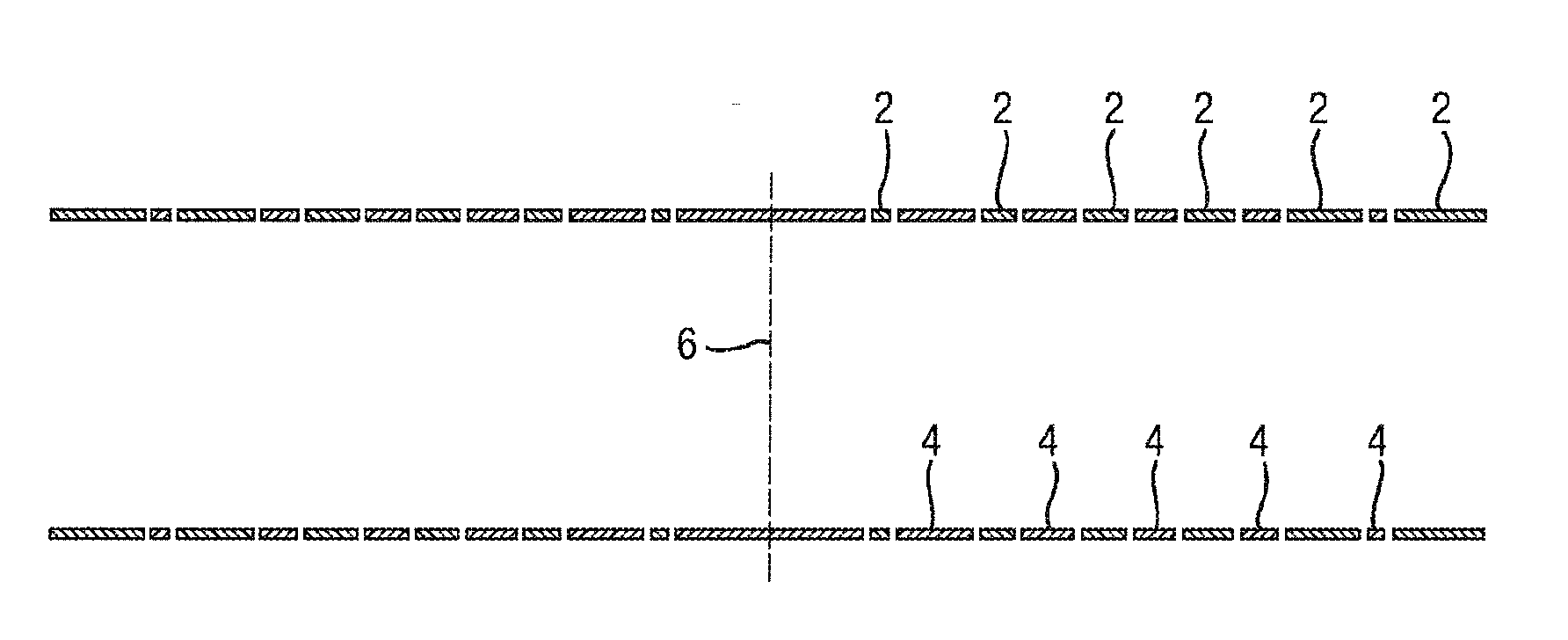
[0111]In order to illustrate the present invention the simple case of the so called “perfectron” will now be described. A “perfectron” is a cylindrical device having a parabolic potential function arranged along the length of its central axis and having defined potential surfaces at the front and rear ends of the device.

[0112]FIG. 1 shows a preferred embodiment of a “perfectron” on the right hand side of the vertical dashed line. The “perfectron” comprising two sets of concentric ring electrodes 2,4 arranged along a longitudinal axis of the device and having front and rear equipotential surfaces. Alternate electrodes in the device form the first set of electrodes 4 and are connected a ground potential. The electrodes in this set become progressively shorter in the longitudinal direction of the device as one moves away from the front end 6 of the device, wherein the front end of the device is arranged at the vertical dashed line. The second set of electrodes 2 is connected to the ion...


PUM


Abstract

A method of manufacturing a device for manipulating charged particles using an axial electric field as they travel along a longitudinal axis of the device is disclosed. The method comprises providing first electrodes of different lengths, supplying different voltages to these electrodes and arranging grounded electrodes between the first electrodes in order to form the desired axial potential profile.

Description

CROSS-REFERENCE TO RELATED APPLICATION[0001]This application claims priority from and the benefit of United Kingdom patent application No. 1308847.1 filed on 16 May 2014 and European patent application No. 13167991.2 filed on 16 May 2014. The entire contents of these applications are incorporated herein by reference.BACKGROUND TO THE PRESENT INVENTION[0002]The present invention relates to device for manipulating charged particles using an electric field. The preferred embodiment relates to a device for use in a mass spectrometer for manipulating ions.[0003]It is desirable to use electric fields to manipulate ions in mass spectrometers. Typically, the device for manipulating the ions comprises a series of electrodes spaced apart along a longitudinal axis of the device. Voltages are applied to the electrodes in order to form the desired electrical potential profile along the device so as to manipulate the ions in the desired manner. The adjacent electrodes in these devices tend to be ...

Claims


Application Information

Patent Timeline
IPC IPC(8): H01J49/06H01J49/40
CPCH01J49/401H01J49/062H01J49/405H01J49/421
Inventor HOYES, JOHN, BRIAN
Owner MICROMASS UK LTD
Why Eureka
Try Eureka