
Medical manipulator

Inactive Publication Date: 2010-03-25
TERUMO KK
View PDF9 Cites 1081 Cited by
  • Summary
  • Abstract
  • Description
  • Claims
  • Application Information

AI Technical Summary

Benefits of technology

[0014]It is an object of the present invention to provide a medical manipulator which makes it possible to allow a distal-end working unit to rotate endlessly within an infinite angular range about a roll axis.
[0019]The distal-end motor may have an output shaft coaxial with the roll axis. Accordingly, the distal-end working unit can be rotated about the roll axis by means of a simple mechanism.
[0020]The distal-end working unit may comprise a power transmitting tubular body coaxially disposed around the distal-end motor and having face gears disposed respectively on axial ends thereof, and a gripper openable and closable about a gripper axis positioned closer to a distal end of the distal-end working unit than the output shaft. The gripper may be opened and closed about the gripper axis by rotation of the power transmitting tubular body. The gripper, which is positioned closer to the distal end of the distal-end working unit than the output shaft, can thus be actuated appropriately.
[0021]The working unit may comprise a proximal-end rotor rotatable by the proximal-end motor, a distal-end rotor disposed in the distal-end working unit for operating the distal-end working unit about one of the at least three axes other than the roll axis, and a flexible member trained around the proximal-end rotor and the distal-end rotor for transmitting power from the proximal-end rotor to the distal-end rotor. The flexible member makes it possible to provide a simple, light, and inexpensive power transmitting mechanism within the working unit.
[0022]The medical manipulator may further comprise a hollow cylindrical member disposed in the joint shaft and rotatable by one of the distal-end motors, for operating the distal-end working unit about one of the at least three axes other than the roll axis. The hollow cylindrical member is less liable to suffer strains, and hence can transmit power highly efficiently.

Problems solved by technology

Therefore, cases that can be handled under usual training practices for endoscopic surgery are limited within a certain range, and a surgeon needs to be trained and highly skilled in order to be able to perform endoscopic surgery on various other cases not within the limited range.
However, since the wire is welded or otherwise fixed at one point to each of the pulleys, the angle through which the pulleys are rotatable is limited by the number of turns of the wire around the pulleys.
Under a torque applied from the motor, the thin wire tends to become elongated, and exhibits low power transmission efficiency, poor response, and has a short service life.

Method used


Image

  • Medical manipulator
  • Medical manipulator
  • Medical manipulator

Examples


Embodiment Construction

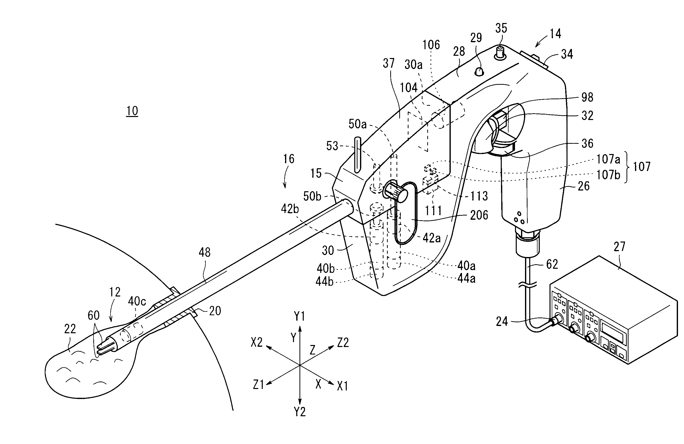
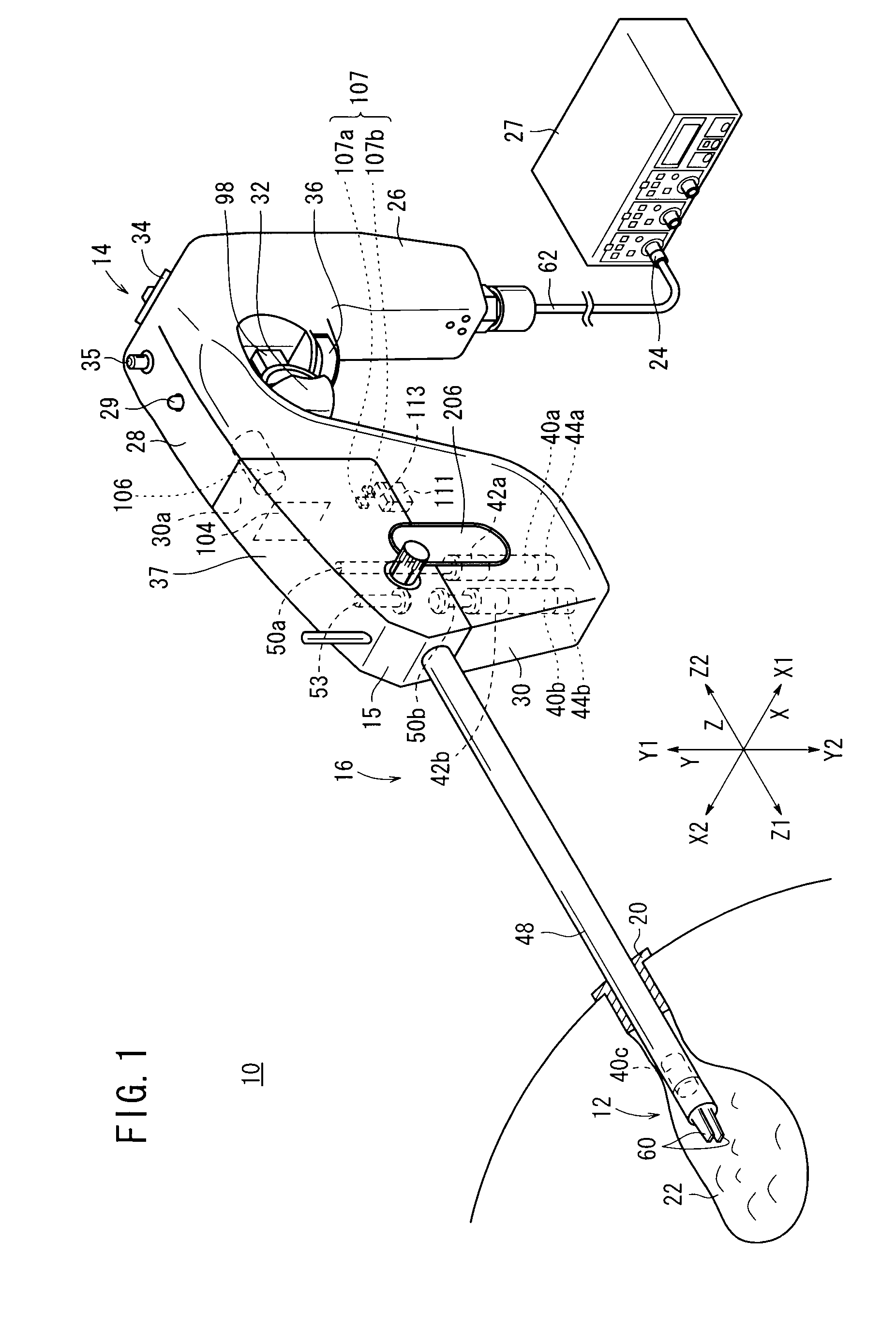
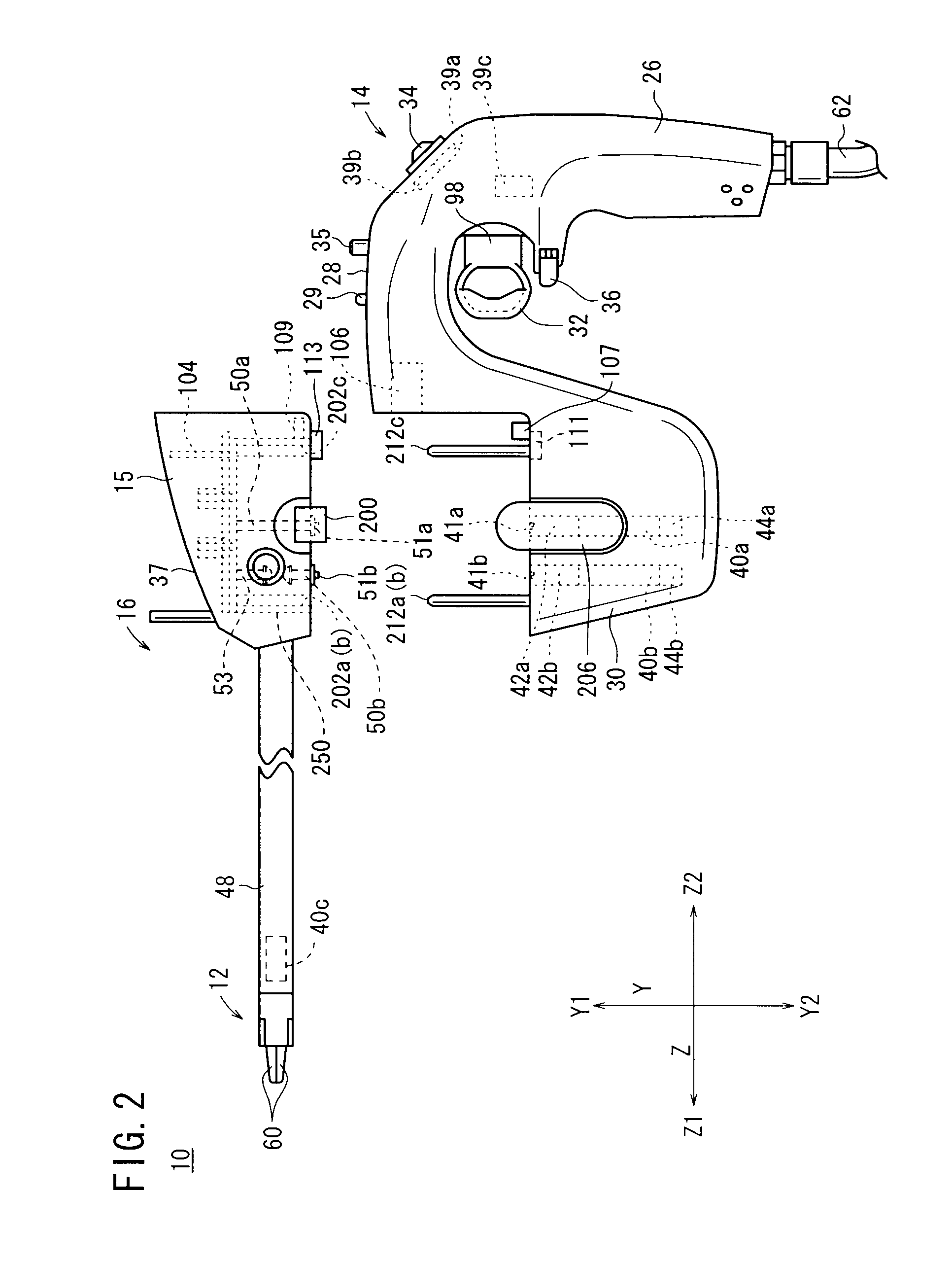
[0035]A medical manipulator according to an embodiment of the present invention will be described below with reference to FIGS. 1 through 11.

[0036]As shown in FIGS. 1, 2, and 3, the medical manipulator 10 has a distal-end working unit 12 for gripping a portion of a living tissue, a curved needle, or the like for performing a certain surgical treatment. The distal-end working unit 12 usually is referred to as a gripping forceps, a needle driver (needle holder), or the like.

[0037]The manipulator 10 comprises an operating unit 14 on a proximal end portion, which is held and operated by a human hand, and a working unit 16 detachably mounted on the operating unit 14. The operating unit 14 is electrically detachably connected to a controller 27 by a connector 24, thereby making up a manipulator system.

[0038]The manipulator 10 basically includes the operating unit 14 and the working unit 16. The controller 27 for electrically controlling the manipulator 10 is connected by the connector 24 ...


PUM


Abstract

A medical manipulator includes an operating unit and a working unit. The operating unit has an actuator block with motors housed therein. The working unit is detachably mounted on the actuator block by a coupler. The working unit comprises a joint shaft that extends from the coupler, and a distal-end working unit mounted on a distal end of the joint shaft. The distal-end working unit has three axes, including a yaw axis, a roll axis about which the distal-end working unit is rotatable and which is positioned closer to a distal end of the distal-end working unit than the yaw axis, and a gripper axis about which a gripper is openable and closable and which is positioned on the distal end. The distal-end working unit can be operated about the roll axis by a motor, which is positioned closer to the distal end than the yaw axis.

Description

CROSS-REFERENCE TO RELATED APPLICATION[0001]This application is based upon and claims the benefit of priority from Patent Application No. 2008-244035 filed on Sep. 24, 2008, in the Japan Patent Office, of which the contents are incorporated herein by reference.BACKGROUND OF THE INVENTION[0002]1. Field of the Invention[0003]The present invention relates to a medical manipulator having an actuator which incorporates proximal-end motors therein, and a working unit detachably coupled to the actuator by a coupler. More particularly, the present invention concerns a medical manipulator having a distal-end working unit on the distal end of a joint shaft which extends from the coupler.[0004]2. Description of the Related Art[0005]According to endoscopic surgery (also called laparoscopic surgery), it is customary to form a plurality of incisions in the body surface of the patient, insert trocars (tubular instruments) into the respective incisions as instrument passage ports, and to introduce ...

Claims


Application Information

Patent Timeline
IPC IPC(8): A61B17/28
CPCA61B19/22A61B2017/2943A61B2017/2936A61B2017/0046A61B34/70
Inventor IMUTA, SHUJI
Owner TERUMO KK
Learn More