Cannulated anchor and system

a cannulated anchor and system technology, applied in the field of implantable medical devices, can solve problems such as damage to surrounding bodily tissues, and achieve the effect of maximizing the accuracy of anchor placemen

Active Publication Date: 2010-03-25
ALASKA HAND RES
View PDF27 Cites 124 Cited by
  • Summary
  • Abstract
  • Description
  • Claims
  • Application Information

AI Technical Summary

Benefits of technology

[0008]Embodiments of the present invention solve problems of the prior art with respect to maximizing the accuracy of anchor placement and anchor alignment in tissue. Embodiments provide anchors that may be optimally forced in, press fit, screwed in or otherwise installed into tissue with minimal damage to the flexible members attached thereto. S

Problems solved by technology

However, recent publications have shown that these sutures can cause damage to sur

Method used


Image

  • Cannulated anchor and system
  • Cannulated anchor and system
  • Cannulated anchor and system

Examples


first embodiment

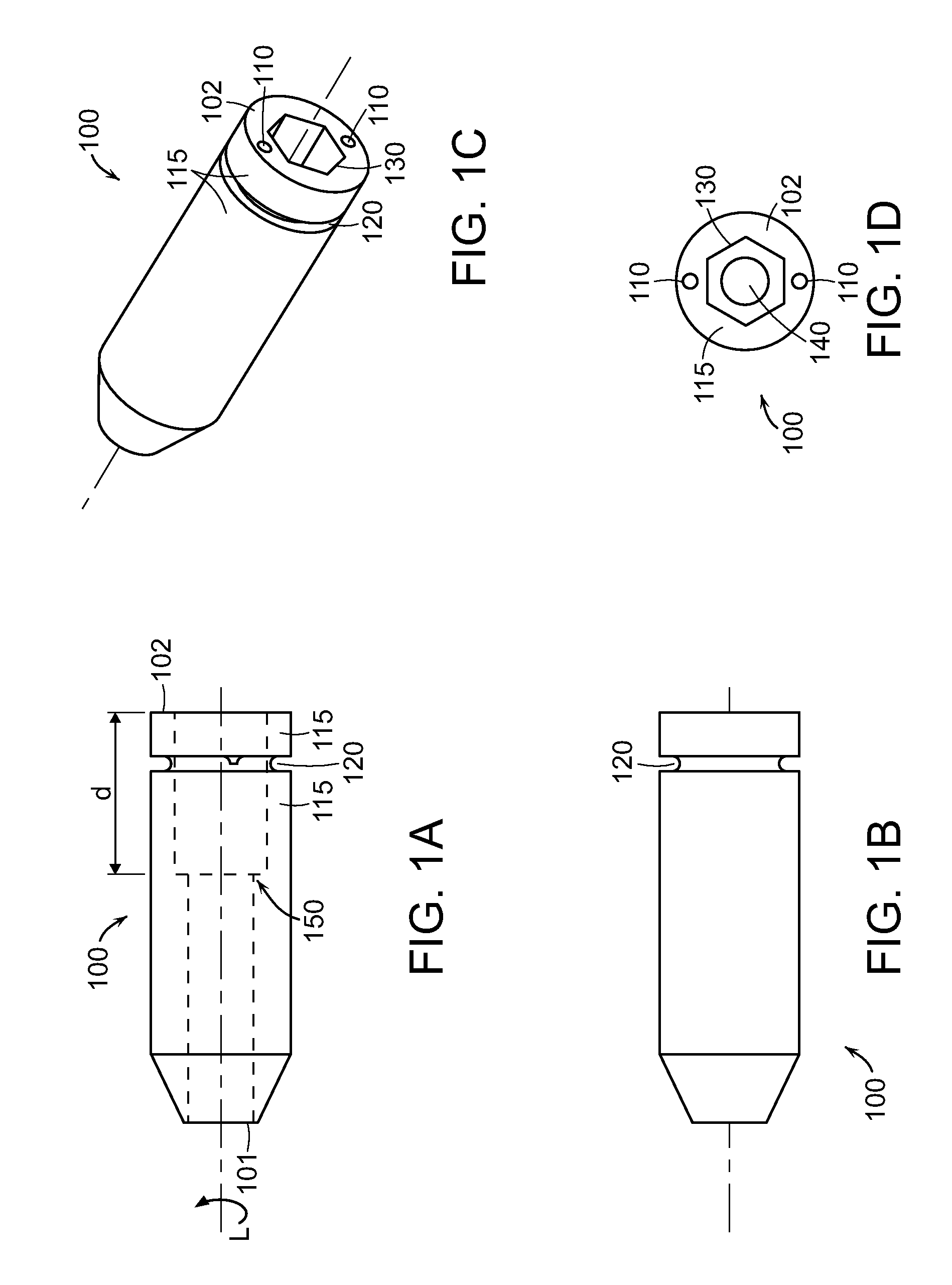
[0026]Regarding a first embodiment, with reference to FIG. 1(a)-(d), inner core anchor portion 100 is shown. Inner core anchor portion 100 has a leading end 101 and trailing end 102; ends 101 and 102 are determined with reference to a defined longitudinal system axis, L, along which cannulated anchor 10 is moved to engage and anchor into tissue. Inner core anchor portion 100, while being essentially cylindrical is, in the embodiment of FIG. 1(a)-(d), shown to be tapered proximate to leading end 101. There may be a variety of reasons to taper the inner core 100, notably for ease of insertion into a pre-existing tissue orifice prepared by a cannulated drill. However, there are circumstances (as shown supra) for which tapering may be undesirable and is, therefore, not considered an essential feature of the disclosed cannulated anchor embodiments. Centrally disposed cannulation 130 is sized to accept a guidewire (not shown) therethrough. When viewing FIGS. 1(c) and 1(d) (as well as 1(a)...

embodiment 100

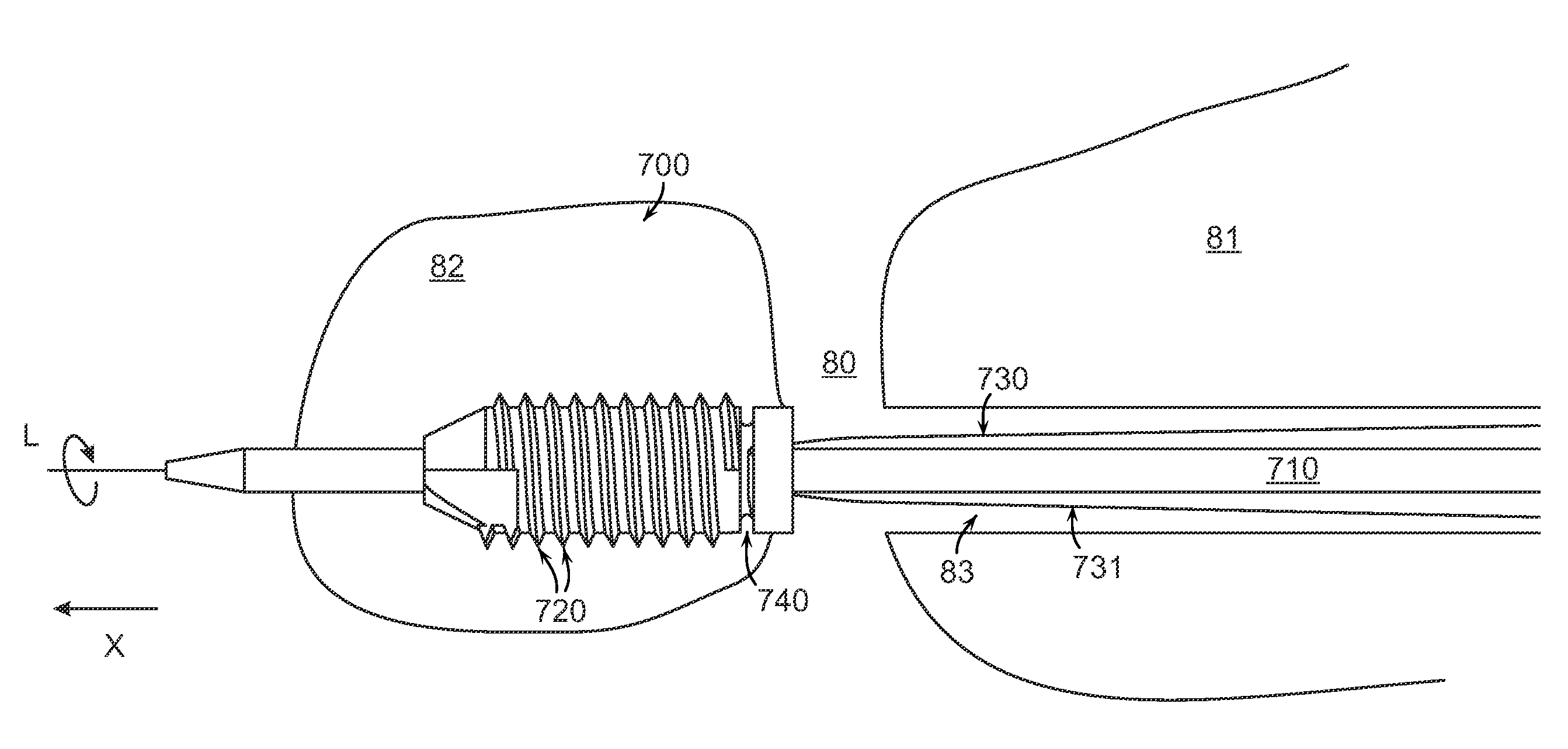
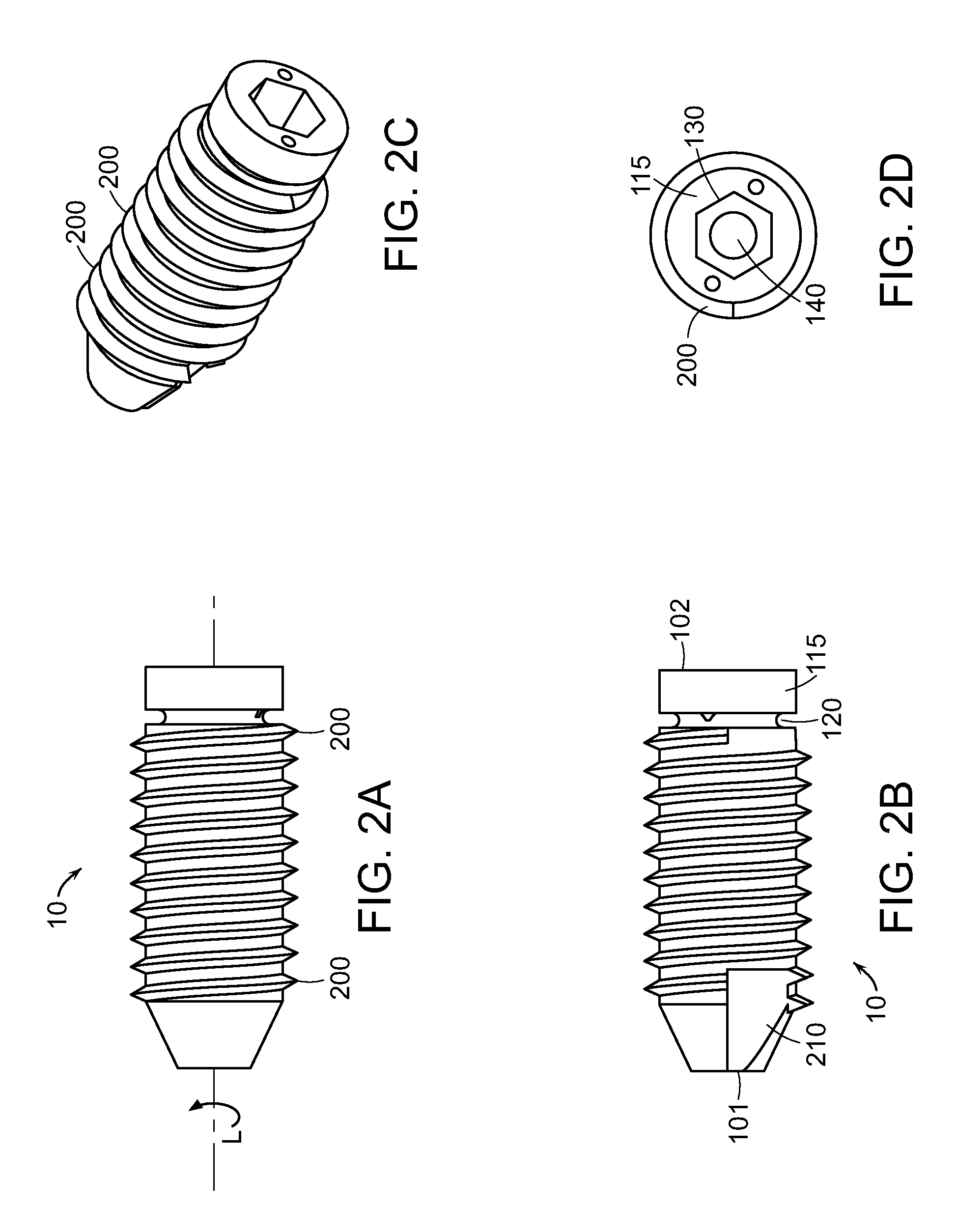
[0030]Referring now to FIG. 2(a)-(d), a cannulated anchor 10 embodiment is comprised of inner core anchor portion embodiment 100 shown in FIG. 1(a)-(d) and an outer anchor portion. The outer anchor portion of FIG. 2(a)-(d) features a plurality of helical ribs 200. Helical ribs 200 are disposed at outer anchor locations (or outer length positions) along axis L. These locations are shown to be disposed between the onset of the taper of inner core anchor portion 100 and circumferential recess 120. Helical ribs 200 extend radially outward from inner core wall 115. The ribs 200, along with cutting edge 210, provide an outer surface for cannulated anchor 10 that effects anchoring into tissue by rotating anchor 10 about axis L thereby creating a self-tapped orifice into tissue. Anchor 10 is, in effect, screwed into the tissue orifice created by rotating anchor 10. Rotation is accomplished by applying torque to an installer when engaged with anchor 10 via the placement of a portion (sometim...


PUM


Abstract

Cannulated anchors are provided that may be optimally forced in, press fit, screwed in or otherwise installed into tissue with minimal damage to the flexible members or sutures attached thereto. Systems for installing at least one flexible member into tissue include the cannulated anchor, the at least one flexible member capable of being received by the cannulated anchor; and an installer with a driver head insertable into the cannulation of the anchor proximate the trailing end and with an essentially longitudinal cannulation centrally disposed along the axis and sized to accept a guidewire therethrough. Movement of the installer about the longitudinal axis causes corresponding movement of the cannulated anchor such that the outer surface of the cannulated anchor is capable of effecting anchoring into the tissue.

Description

[0001]This application claims priority from U.S. Provisional Patent Application Ser. No. 61 / 067,911, filed Mar. 3, 2008, which is incorporated herein by reference.TECHNICAL FIELD[0002]The present invention relates to implantable medical devices, and more specifically, to a system for securing flexible members / sutures with tissue.BACKGROUND ART[0003]Suture anchors are commonly used in orthopedic surgery to affix suture to bone. Sutures may then be affixed to tissue or a secondary implant, thereby securing the tissue or device to bone. Often, the suture anchor is used to repair an injured tendon or ligament. Alternatively, the anchor may be installed alongside an autograft, allograft, xenograft or synthetic tissue implant using interference to secure the material within a bone tunnel.[0004]External features along the anchor body are known in the art for effecting engagement of a suture anchor with tissue. Examples of these features, which may be used combination, include self-tapping ...

Claims


Application Information

Patent Timeline
IPC IPC(8): A61B17/86A61B17/58
CPCA61B17/0401A61B2017/0409A61B2017/0458A61B2017/044A61B2017/0445A61B2017/0427
Inventor MCNAMARA, MICHAEL G.MUNOZ, AVERY B.
Owner ALASKA HAND RES
Why Eureka
Try Eureka