Bone implant

a bone implant and bone technology, applied in the field of bone implants, can solve the problems of hip fractures and death in the elderly, and achieve the effect of minimizing damage to healthy bones

Inactive Publication Date: 2010-03-25
N M B MEDICAL APPL
View PDF76 Cites 211 Cited by
  • Summary
  • Abstract
  • Description
  • Claims
  • Application Information

AI Technical Summary

Benefits of technology

[0064]A broad aspect of some embodiments of the invention relates to inj

Problems solved by technology

Hip fractures are a leading (indir

Method used


Image

  • Bone implant
  • Bone implant
  • Bone implant

Examples


Embodiment Construction

Overview

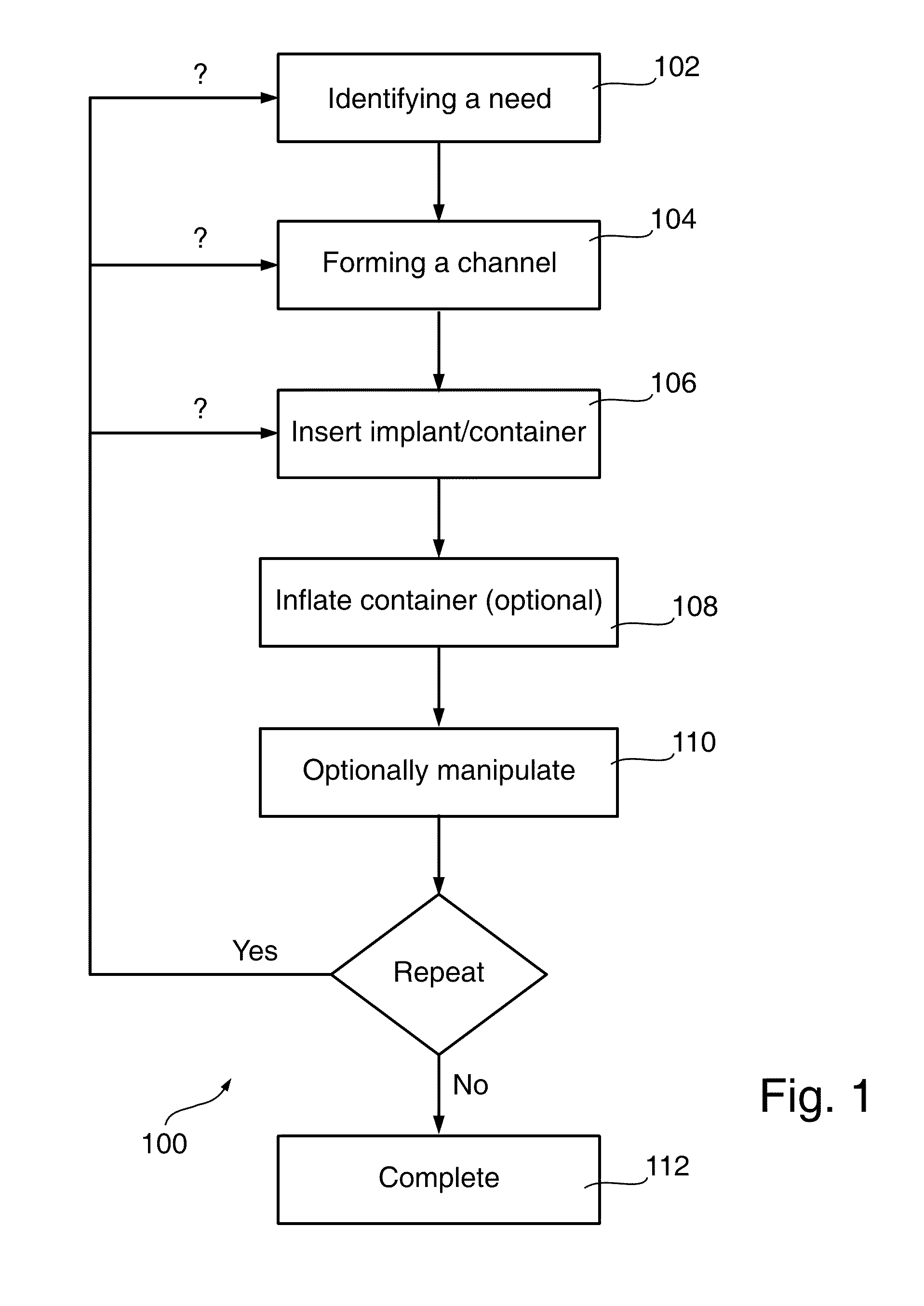
[0175]FIG. 1 is a flowchart 100 of a method of strengthening a bone, for example to prevent fractures, in accordance with an exemplary embodiment of the invention. In brief, the method includes identifying a need (102), forming a channel in the bone (104), inserting an implant and / or a container (106), optional inflating the container using cement (108), optional repeating or otherwise manipulating the container (110) and completing the procedure (112).

Exemplary Prophylactic Treatment

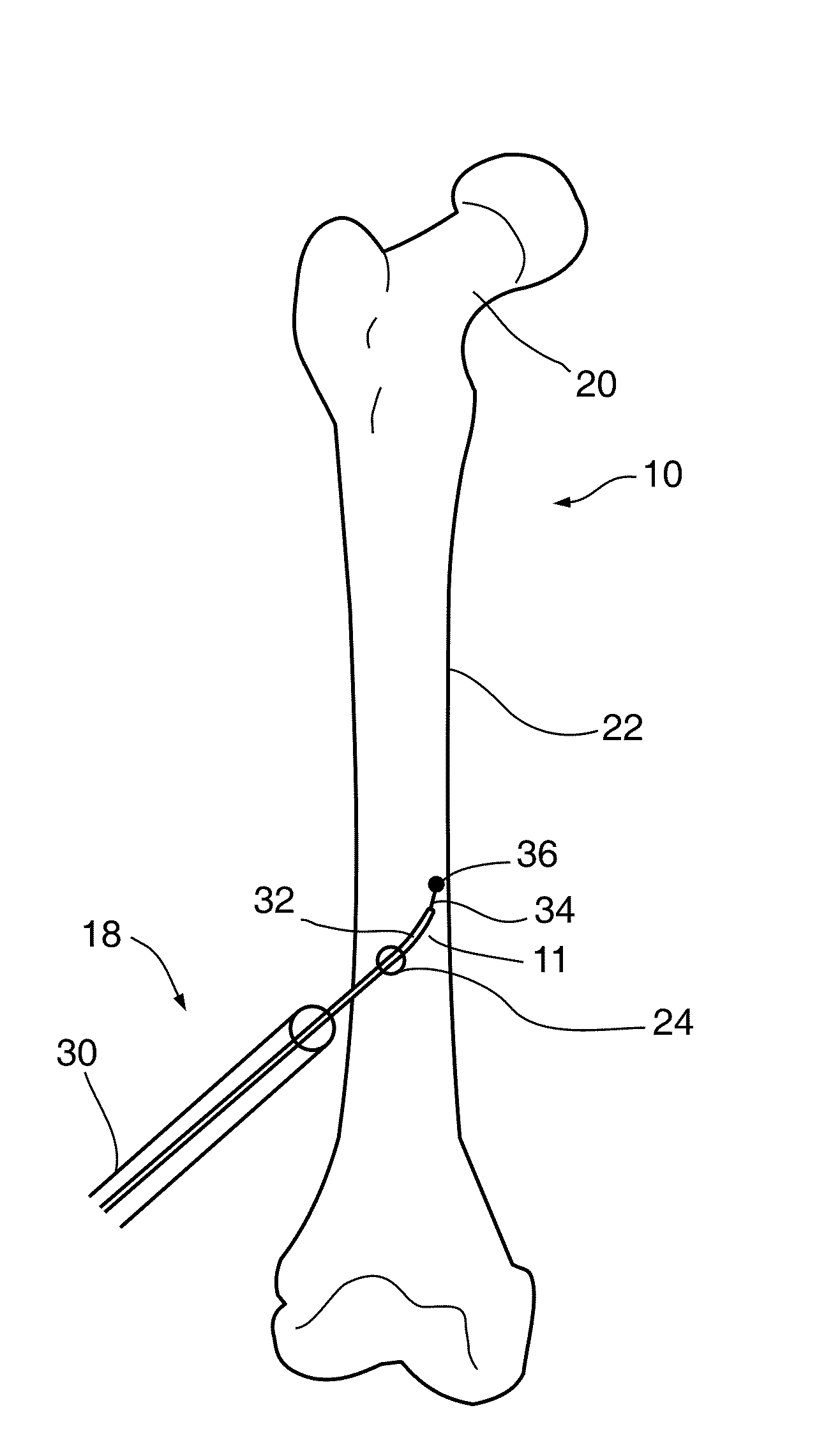
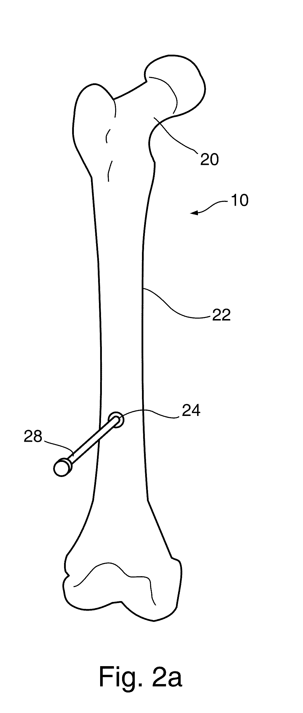
[0176]The method schematically depicted in FIG. 1 is explained for a specific prophylactic treatment of a non-fractured femur 10 as depicted in FIGS. 2A-2M. However, the treatment is not limited for preventive purposes, and may also be used for the treatment of broken bones. In these figures is described the implantation of an implant 12 of the some embodiments of the present invention. FIG. 2I depicts the implant fully assembled and deployed in a longitudinal channel 11 running through femur 10...


PUM


Abstract

A method of long bone strengthening and a composite implant for such strengthening. Also disclosed is a kit for building a composite implant in-situ in long bones. In an exemplary embodiment of the invention, the implant comprises a plurality of rigid tensile rods, in matrix of cement and surrounded by a partially porous bag.

Description

RELATED APPLICATIONS[0001]The present application claims priority from IL Patent Application No. 181211 filed on Feb. 7, 2007, and from IL Patent application No. 182821 filed 26 Apr. 2007 the disclosures of which are incorporated herein by reference.FIELD OF THE INVENTION[0002]The present invention relates to methods and devices for strengthening of long bones, for example effective for preventing fractures of bones.BACKGROUND OF THE INVENTION[0003]Hip fractures are a leading (indirect) cause of death in the elderly. Typically, Osteoporosis, in which the inner trabecular structure of the bone is destroyed, underlies the hip fracture. Furthermore, it is known that a fracture in one hip is a reliable indicator of danger of fracture in the other hip.[0004]A typical bone structure is an outside of hard cortical bone and an inside formed of softer bone, such as trabecular bone and / or marrow or other non-structural tissue. Various blood vessels are also provided in bone.[0005]U.S. Pat. No...

Claims


Application Information

Patent Timeline
IPC IPC(8): A61B17/56
CPCA61B17/1615A61F2310/00353A61B17/1626A61B17/1631A61B17/1633A61B17/1637A61B17/164A61B17/1642A61B17/1644A61B17/1668A61B17/7095A61B17/7097A61B17/7098A61B17/72A61B17/7233A61B17/7258A61B17/7266A61B17/7291A61B17/742A61B19/54A61B2017/00867A61B2017/1648A61B2019/306A61B2217/005A61F2002/2825A61F2002/2832A61F2002/30583A61F2210/0085A61B17/1617A61B2090/036A61B90/39
Inventor BEYAR, MORDECHAYGLOBERMAN, ORENEINAV, ELAD
Owner N M B MEDICAL APPL
Why Eureka
Try Eureka