Flush toilet

Active Publication Date: 2010-04-01
TOTO LTD
View PDF3 Cites 9 Cited by
  • Summary
  • Abstract
  • Description
  • Claims
  • Application Information

AI Technical Summary

Benefits of technology

[0006]In localities with extremely low water main pressure, however, there is a problem in that even increasing the volume of spouted flush water does not enable sufficient flushing of the toilet. That is, even if

Problems solved by technology

In localities with extremely low water main pressure, however, there is a problem in that even increasing the volume of spouted flush water does not enable sufficient flushing of the toilet.
That is, even if low flow rate spout water is spouted over a long duration from a jet spout, in particular, no siphoning effect can be induced in the waste trap pipe, and waste in the bowl portion cannot be adequately discharged.
In the flush water supply device set forth in U.S. Pat. No. 2,874,207, on the other hand, a pressure

Method used


Image

  • Flush toilet
  • Flush toilet
  • Flush toilet

Examples


first embodiment

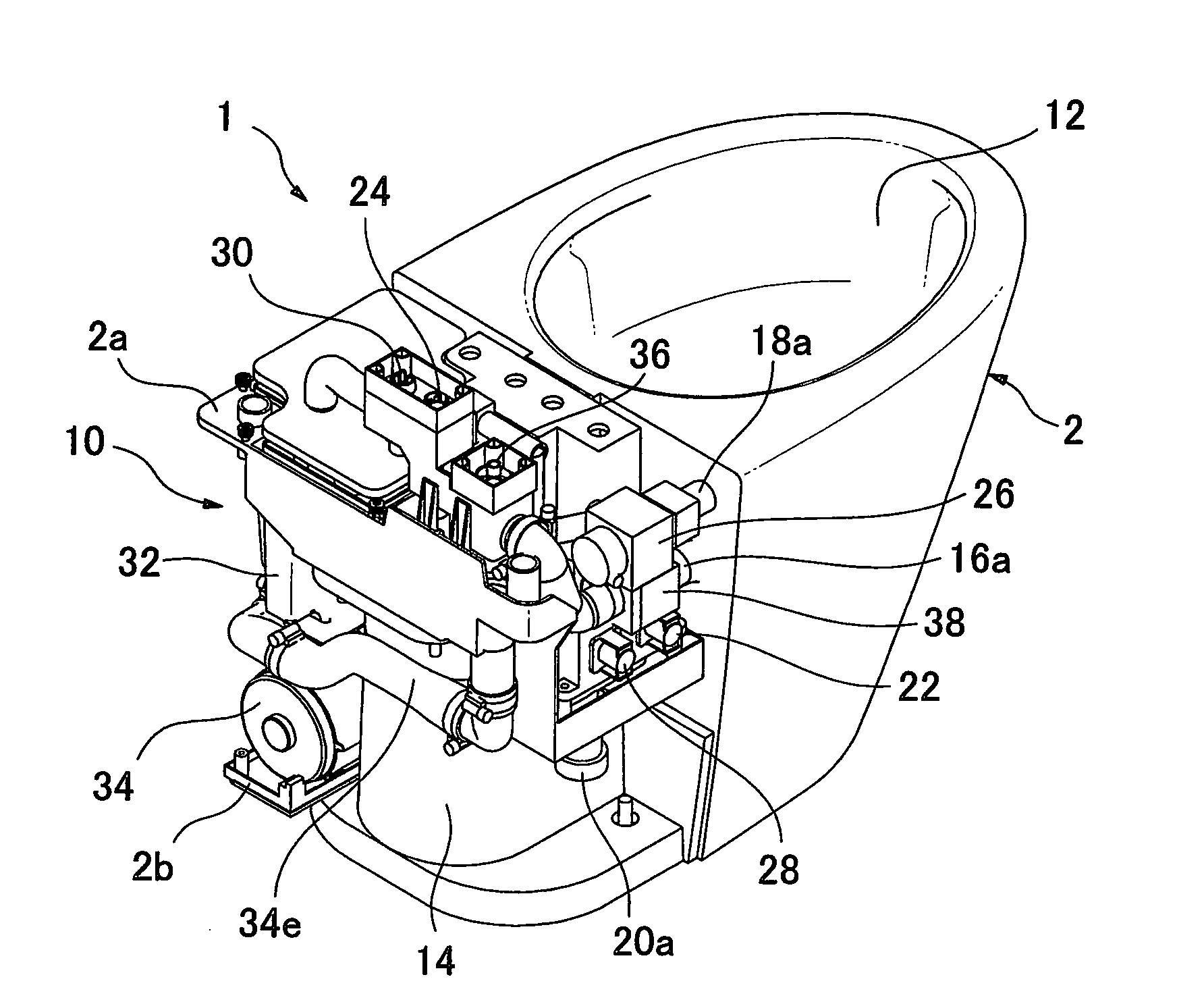
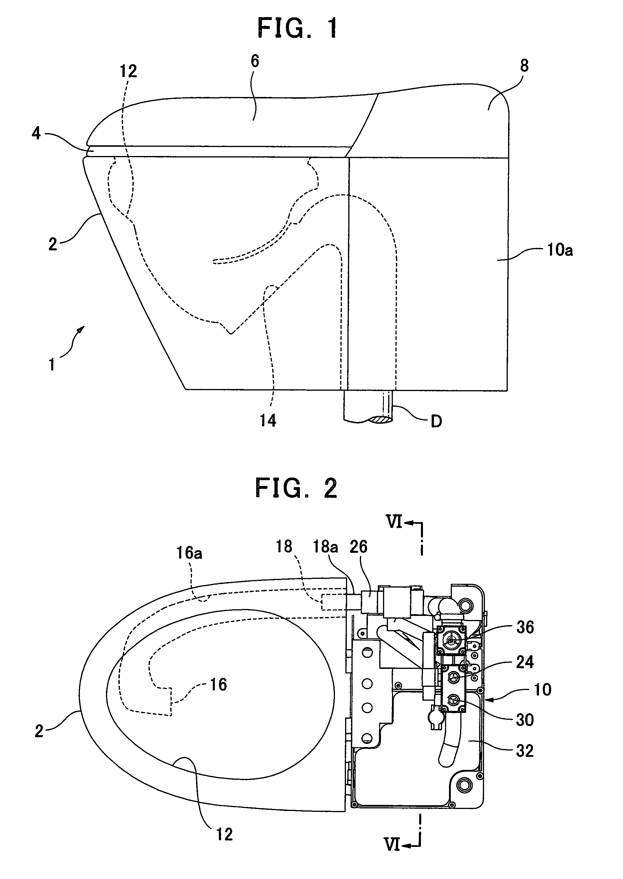
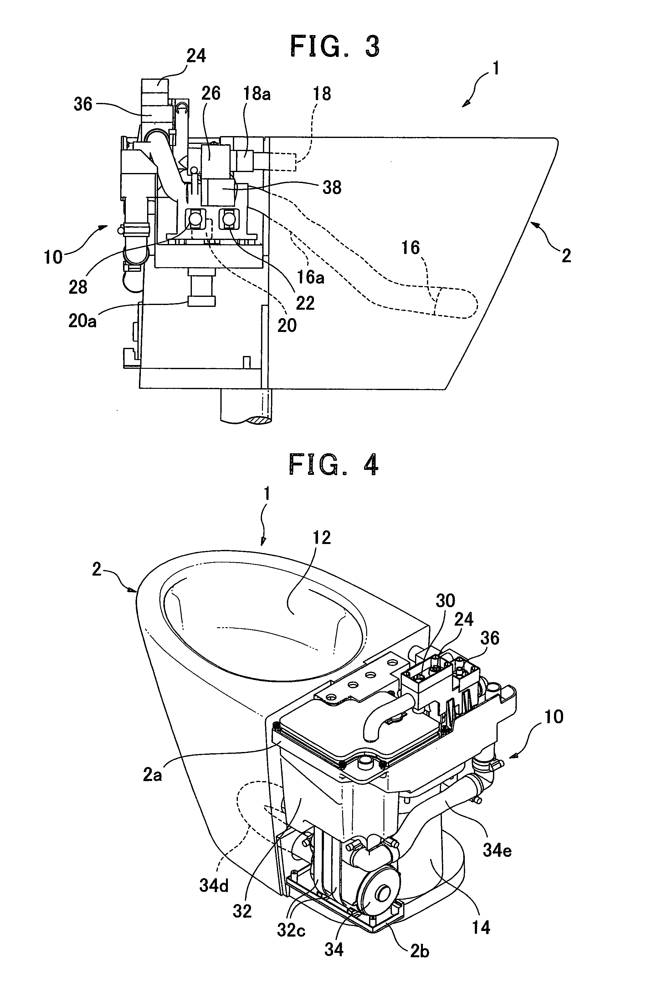
[0036]Next, referring to the attached drawings, we will discuss a flush toilet according to the present invention. FIG. 1 is a right side elevation of a flush toilet according to the present embodiment. FIG. 2 is a top plan view of a flush toilet according to the present embodiment, and FIG. 3 is a left side elevation thereof. FIG. 4 is a perspective view looking down diagonally from the rear right of a flush toilet according the present embodiment; FIG. 5 is a perspective view looking down diagonally from the rear left thereof. In addition, FIG. 6 is a cross section along line VI-VI in FIG. 2. FIG. 7 is a block diagram showing the water supply system for the rim water spouting and the jet water spouting. Note that FIGS. 2 through 6 show a flush toilet according to the present embodiment in which the toilet seat, the cover, the bidet (“Washlet”), and side panels are removed.

[0037]As shown in FIG. 1, a flush toilet 1 according to the first embodiment of the present invention has a fl...

second embodiment

[0100]As show in FIG. 17, a flush toilet 100 according to the present invention has a flush toilet main body 102 and a functional portion disposed at the rear of the flush toilet main body 102. A bowl portion 112, a drain trap pipe 114, a jet spouting port 116, and a rim water spouting port 118 are formed on the flush toilet main body 102.

[0101]The flush toilet 100 according to the second embodiment of the present invention is directly connected to the water main supplying flush water, and flush water is expelled from a rim water spouting port 118 by water main supply pressure. Regarding jet-spouted water, flush water held in a holding tank built into the functional portion 110 is pressurized by a pressurizing pump and expelled from a jet water spouting port 116 in a large flow rate.

[0102]Next, we discuss the constitution of the functional portion 110. As shown in FIG. 17, a constant flow valve 120, a rim spout water electromagnetic valve 122, a tank water supply electromagnetic val...


PUM


Abstract

A flush toilet in which an appropriate amount of water is supplied and that can be installed in an area where water pressure is low. The flush toilet is flushed with pressurized flush water and has a flush toilet body having a bowl and a drain trap pipe path; a pressurizing pump for pressurizing flush water to be jetted out; a water storage tank for storing flush water to be pressurized; flush control means for causing rim water discharge to be performed for a predetermined rim water discharge time by water supply pressure of running water and also causing jet water discharge to be made to flush the bowl; flush water replenishing means for replenishing, after the bowl is flushed, flush water to the water storage tank from the running water to thereby return the amount of flush water stored in the water storage tank to a specified level; timing means for measuring a water replenishing time after the flush water replenishing is started until the amount of flush water stored in the water storage tank return to the specified level; and water discharge time regulation means for regulating the rim water discharge time based on the water replenishing time.

Description

TECHNICAL FIELD[0001]The present invention relates to a flush toilet, and more particularly to a flush toilet flushed with pressurized flush water.BACKGROUND ART[0002]In recent years, “water main direct-pressure” type flush toilets, in which flush water is supplied directly from a water main, have become more prevalent. In this type of water main direct pressure-type flush toilet, the toilet is generally flushed in a sequence whereby water is spouted from a rim spout at the top of the bowl portion, then from a jet spout at the bottom portion of the bowl portion, then a second time from the rim spout, each for a predetermined time. Because water main direct pressure-type flush toilets do not require a tank for holding all of the flush water for a single flush, they have the advantage that they can be made more compact, but on the other hand have the problem that it may be difficult to supply flush water at an adequate flow rate in localities with low water main pressure, making them ...

Claims


Application Information

Patent Timeline
IPC IPC(8): E03D3/10
CPCE03D5/01E03D2201/30E03D5/10E03D3/00E03D11/02
Inventor OKUBO, MAYUUSHIJIMA, YOSHIKAZUSATO, YUICHIKATO, YOSHINOBUHAYASHI, RYOSUKEHARADA, AYAKO
Owner TOTO LTD
Why Eureka
Try Eureka