Method and system for heating a sauna

Inactive Publication Date: 2010-04-01
KIM BYUNG T
View PDF14 Cites 1 Cited by
  • Summary
  • Abstract
  • Description
  • Claims
  • Application Information

AI Technical Summary

Benefits of technology

[0016]The present invention overcomes these limitations by introducing a method and system for heating a heat retaining structure (“a heat source”) having a high heat capacity and used to radiantly heat a room such as a sauna, whereby the structure is heated in an oven using an electrical source comprising a plurality of electrical heating elements. In addition, air within the oven is circulated

Problems solved by technology

Therefore, when a part fails, the entire spa system often must be shut down.
Because of the high temperatures involved, such shutdowns can be lengthy because of the time required for cooling down the oven to a safe temperature, human intervention for repair, and subsequent heat up.
Further, present systems also require frequent maintenance, and therefore require periodic shutdowns.
Even when permitted, such an open flame presents a significant fire and health hazard.
Further, the flame is generated by a burner disposed at a fair distance from the oven, which requires duct work of significant length and complexity.
Standard duct work is prone to leaks, cracking, and heat loss at these high temperatures.
The result is that the overa

Method used


Image

  • Method and system for heating a sauna
  • Method and system for heating a sauna
  • Method and system for heating a sauna

Examples


Embodiment Construction

[0020]The present invention is directed to a system and method for heating a room and, in particular, heating a sauna.

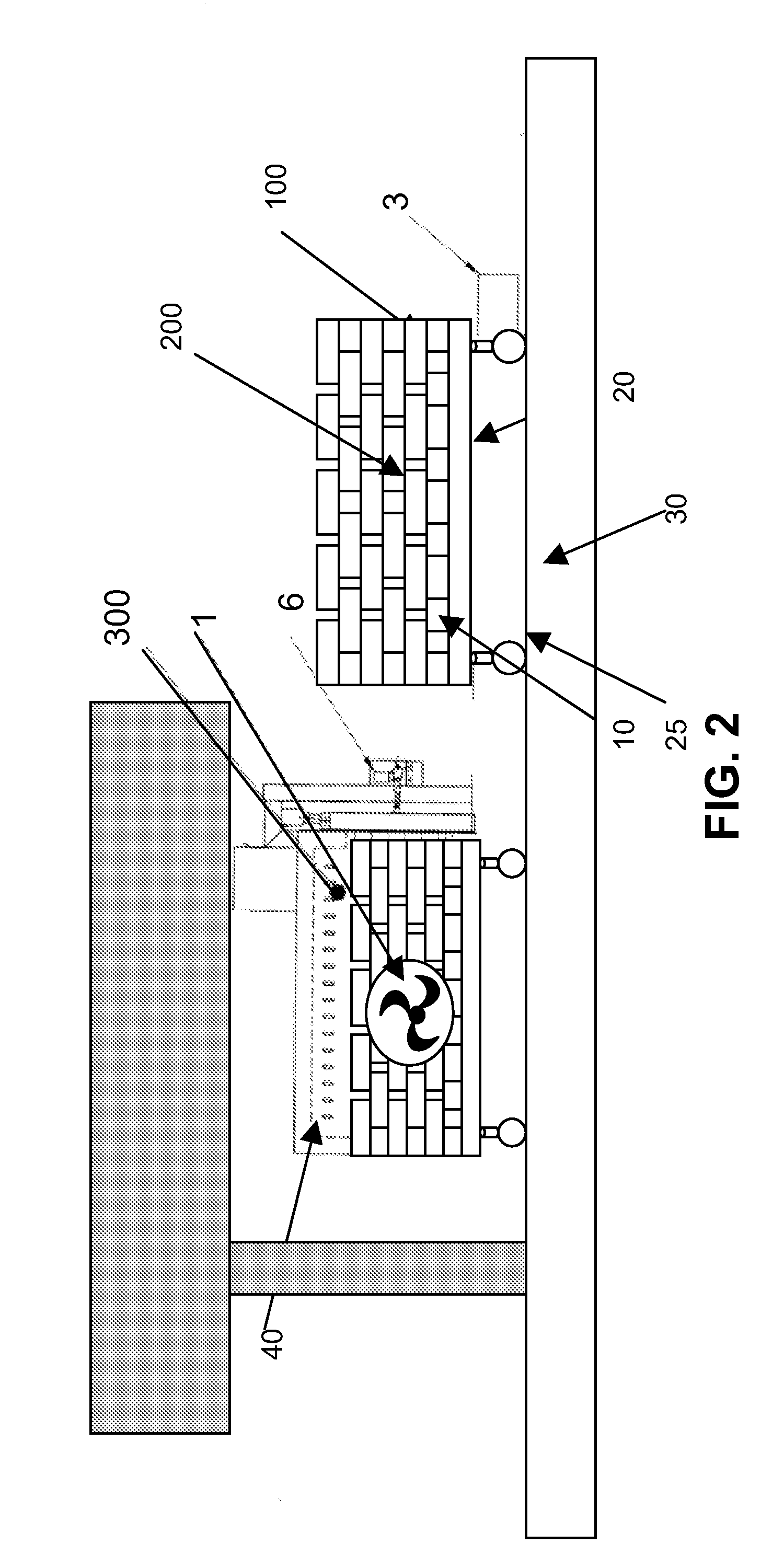
[0021]In general, the present invention is further directed to a system and associated methods for convection heating a collection of heat-retaining objects formed as a structure and serving as a heating source, transporting the structure to a second room, allowing the structure to radiantly heat the second room, and then returning the structure to the first room for re-heating.

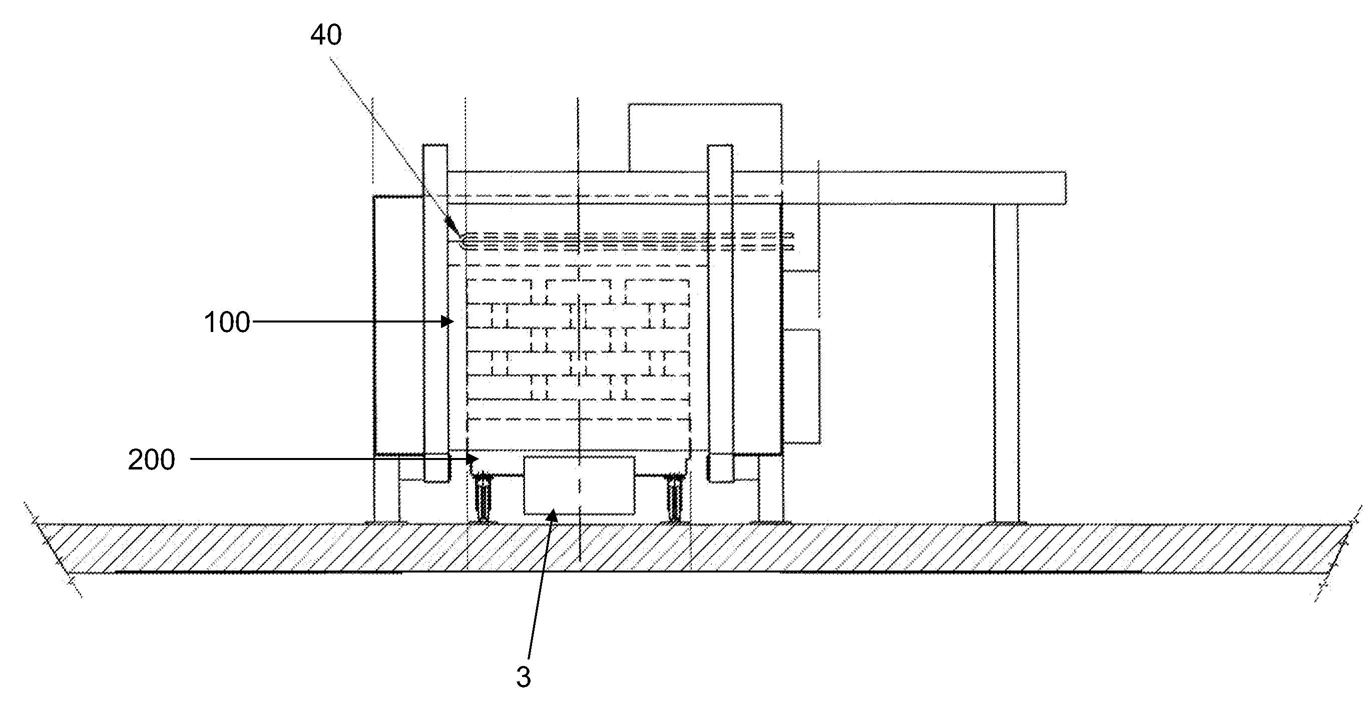
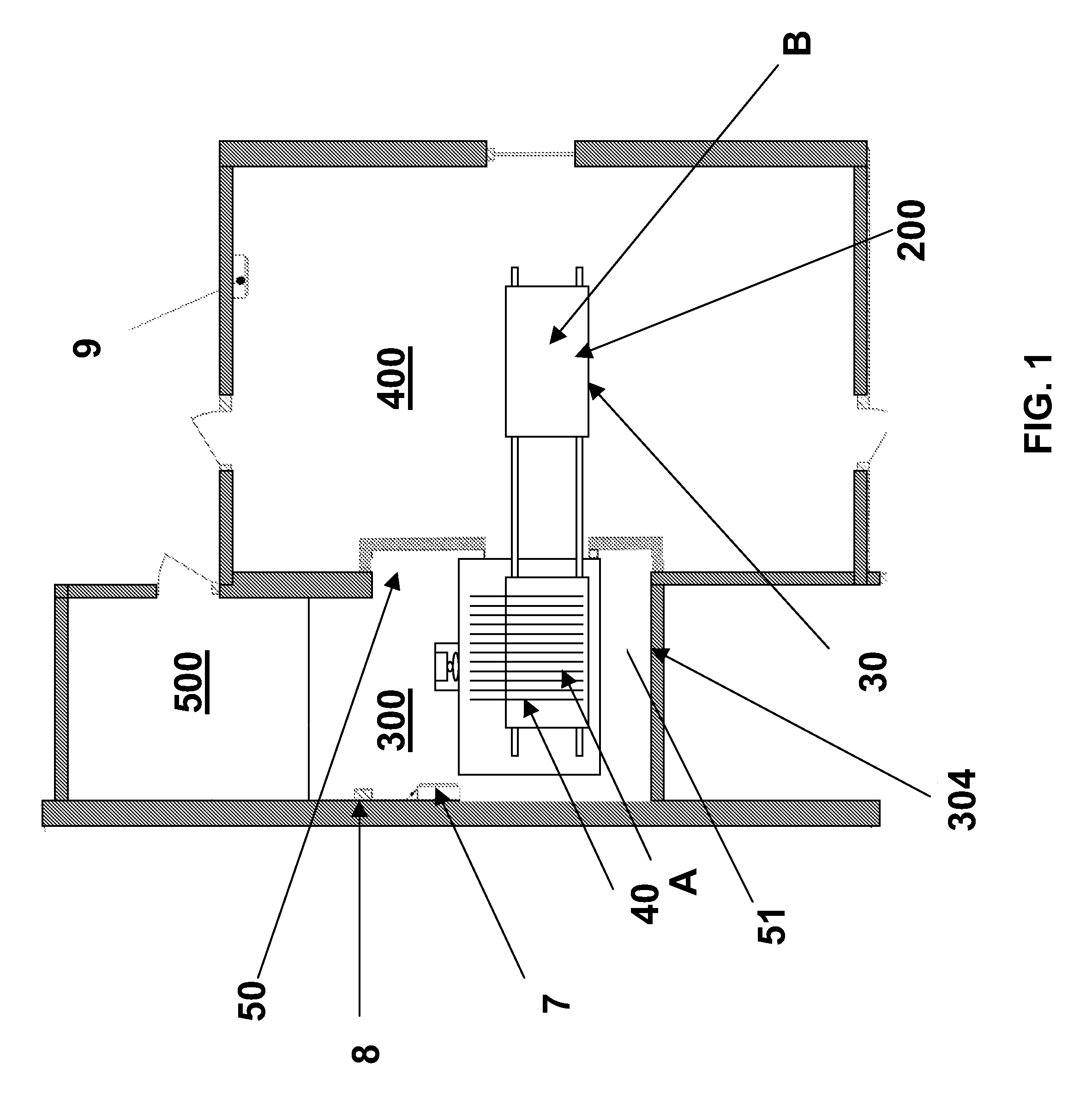
[0022]The reader is directed to FIG. 1, which shows the relative positions of the various rooms including oven 300 and sauna 400. Oven 300 is nominally 10 feet by 10 feet by 10 feet. In the preferred embodiment, oven 300 is made of heavy duty carbon steel frame with a carbon steel shell 308, an inside lining 304, and a 6 inch spun ceramic fiber core 306, although other structures providing similar physical and thermal properties may alternatively be used.

[0023]Sauna 400 is a room in close prox...


PUM


Abstract

The present invention is directed to a system and methods for heating a room such as a spa or a sauna. In the present invention, a heating source placed upon a transportable vehicle is electrically heated in an oven and transported to the room via rail. Heat from the payload is dissipated into the room and, after the ambient temperature lowers back down, the vehicle and payload are returned to the over for subsequent re-heating.

Description

[0001]The present invention claims priority to provisional U.S. Application No. 61 / 100,938, filed on Sep. 29, 2008, which is incorporated herein by reference.BACKGROUND OF THE PRESENT INVENTION[0002]1. Field of Invention[0003]This invention pertains to a structure for heating a sauna wherein a stack of bricks with high heat retention properties is selectively shifted between an oven and a sauna for heating the latter.[0004]2. Description of the Prior Art[0005]Heated spas and saunas have been used for many years for different therapeutic purposes. Various methods have been used to heat such rooms or other areas with a spa. One common method presently used is to indirectly heat a sauna by first convectionally elevating the temperature of a movable heat source to a high temperature in an oven, transporting the heated source to the room, and allowing the source to radiate its heat, thereby providing a safe dry heating means for the sauna.[0006]As can be appreciated, because of size and ...

Claims


Application Information

Patent Timeline
IPC IPC(8): A61H33/06
CPCA61H33/063
Inventor KIM, BYUNG T.
Owner KIM BYUNG T
Why Eureka
Try Eureka