
Method for manufacturing plugged honeycomb structure, and plugged honeycomb structure

Active Publication Date: 2016-09-22
NGK INSULATORS LTD
View PDF3 Cites 6 Cited by
  • Summary
  • Abstract
  • Description
  • Claims
  • Application Information

AI Technical Summary

Benefits of technology

The present invention relates to a honeycomb structure with a segmented honeycomb structure and a trapping layer forming slurry. The honeycomb structure can be used as a catalyst or a filter. The segmented honeycomb structure can be prepared by bonding multiple honeycomb segments and processing the outer edge of the bonded member. The trapping layer forming slurry can be used to form the trapping layer of the honeycomb structure. The honeycomb structure can have various shapes, such as a circle, and the cross-sectional shape of the honeycomb structure can be designed as desired. The invention also provides methods for preparing the honeycomb structure and the trapping layer forming slurry. The technical effects of the invention include improved catalyst or filter performance, reduced pressure drop, and improved pore size distribution.

Problems solved by technology

According to the manufacturing methods described in Patent Documents 1 to 4 as stated above, they can suppress penetration of slurry to form a trapping layer into the pores of the porous supporting body (partition wall), but it is difficult to suppress the penetration sufficiently.
This leads to a problem that the trapping layer becomes densified.
Further as compared with the case of dip-coating of slurry to the partition wall base material, it tends to be difficult to form a trapping layer that is uniform in thickness when slurry is sprayed to the partition wall base material for deposition.

Method used


Image

  • Method for manufacturing plugged honeycomb structure, and plugged honeycomb structure
  • Method for manufacturing plugged honeycomb structure, and plugged honeycomb structure
  • Method for manufacturing plugged honeycomb structure, and plugged honeycomb structure

Examples


example 1

[0173]In Example 1, a partition wall base material forming raw material to prepare a honeycomb substrate was firstly prepared. The partition wall base material forming raw material was prepared by mixing 5,000 g of cordierite powder, 300 g of starch as pore former, 100 g of montmorillonite, and 500 g of methylcellulose to be powder (partition wall base material raw material “a”), to which water was added as needed. The cordierite powder had the average particle diameter of 20 μm, and the pore former had the average particle diameter of 25 μm.

[0174]Next, the obtained partition wall base material forming raw material was kneaded by a kneader, and then was pugged by a vacuum pugmill to faun a kneaded material. Next, the obtained kneaded material was extruded to prepare a honeycomb formed body. The honeycomb formed body was such that the partition wall base material thereof after firing had the thickness of 300 and the cell density of 46.5 cells / cm2. The cells of the honeycomb formed bo...

examples 2 to 13 and examples 15 to 18

[0204]In Examples 2 to 13 and Examples 15 to 18, plugged honeycomb structures were manufactured similarly to Example 1 other than that the partition wall base material raw materials and the trapping layer forming slurry in the combination as shown in Table 3 were used.

example 14

[0205]In Example 14, a plugged honeycomb structure was manufactured similarly to Example 1 other than that the partition wall base material raw material and the trapping layer forming slurry in the combination as shown in Table 3 were used and the firing condition was changed. In Example 14, the temperature rising from 1,200 to 1,425° C. during firing of the plugged honeycomb structure after degreasing was performed in 23 hours.


PUM

PropertyMeasurementUnit
Temperatureaaaaaaaaaa
Percent by massaaaaaaaaaa

Abstract

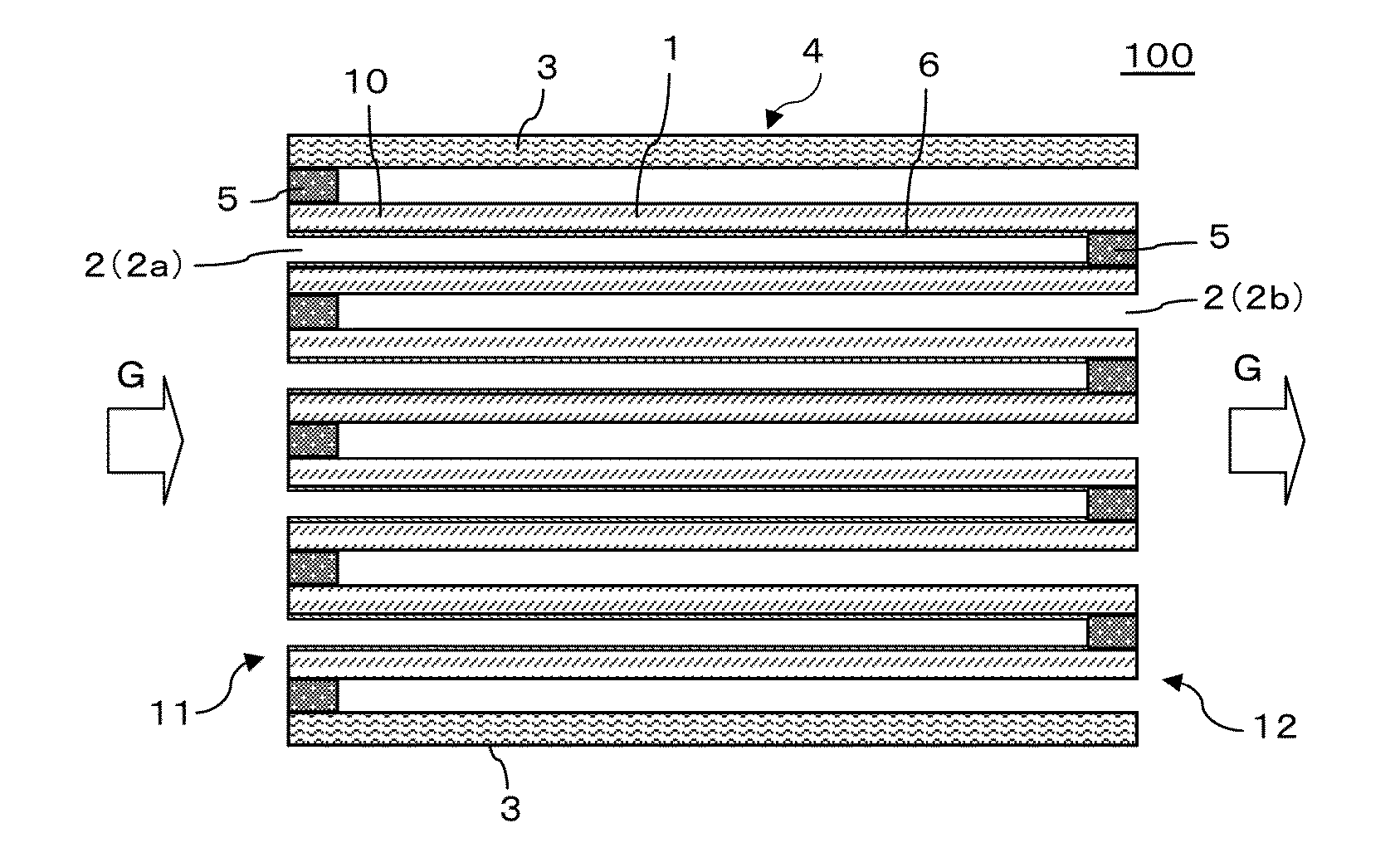
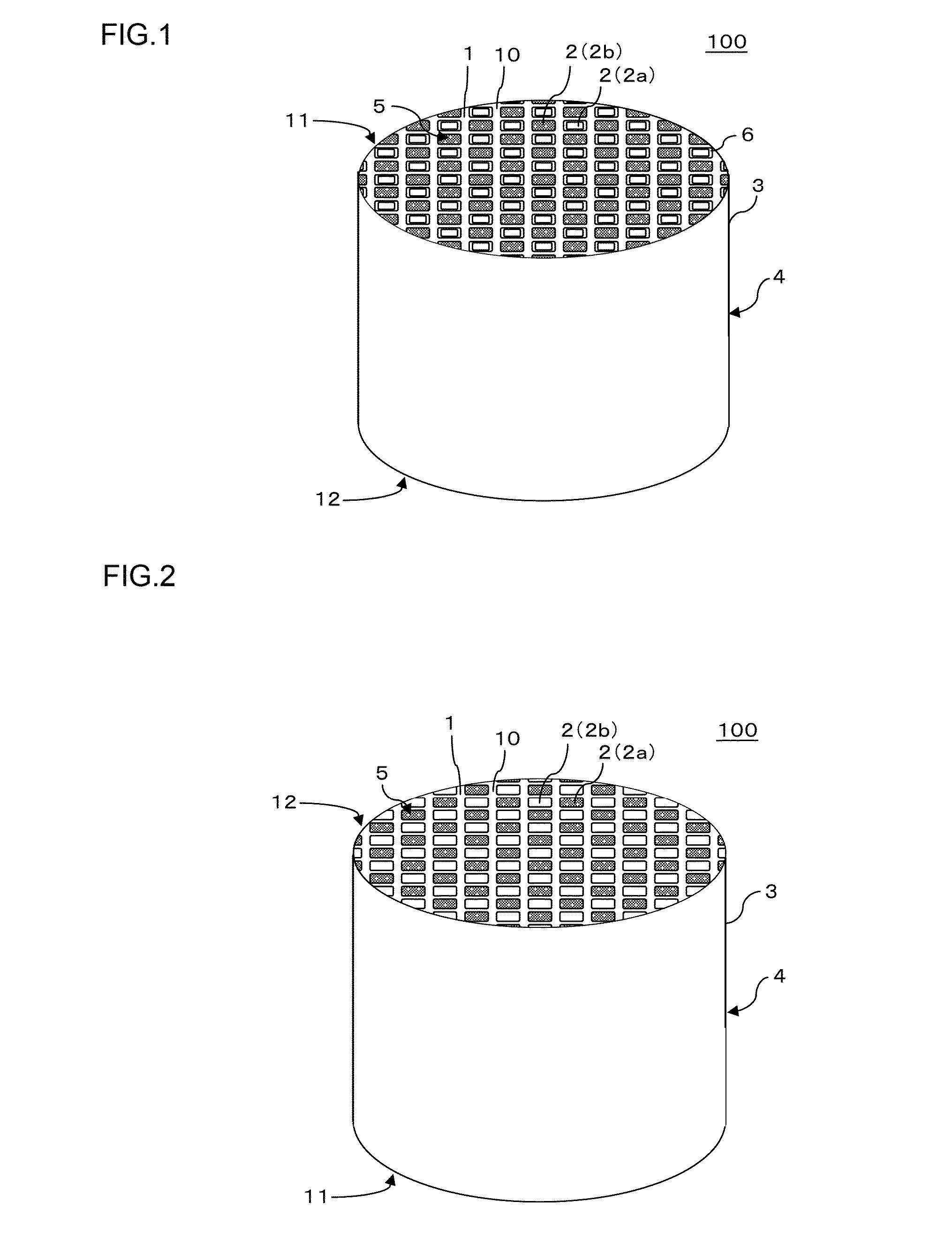
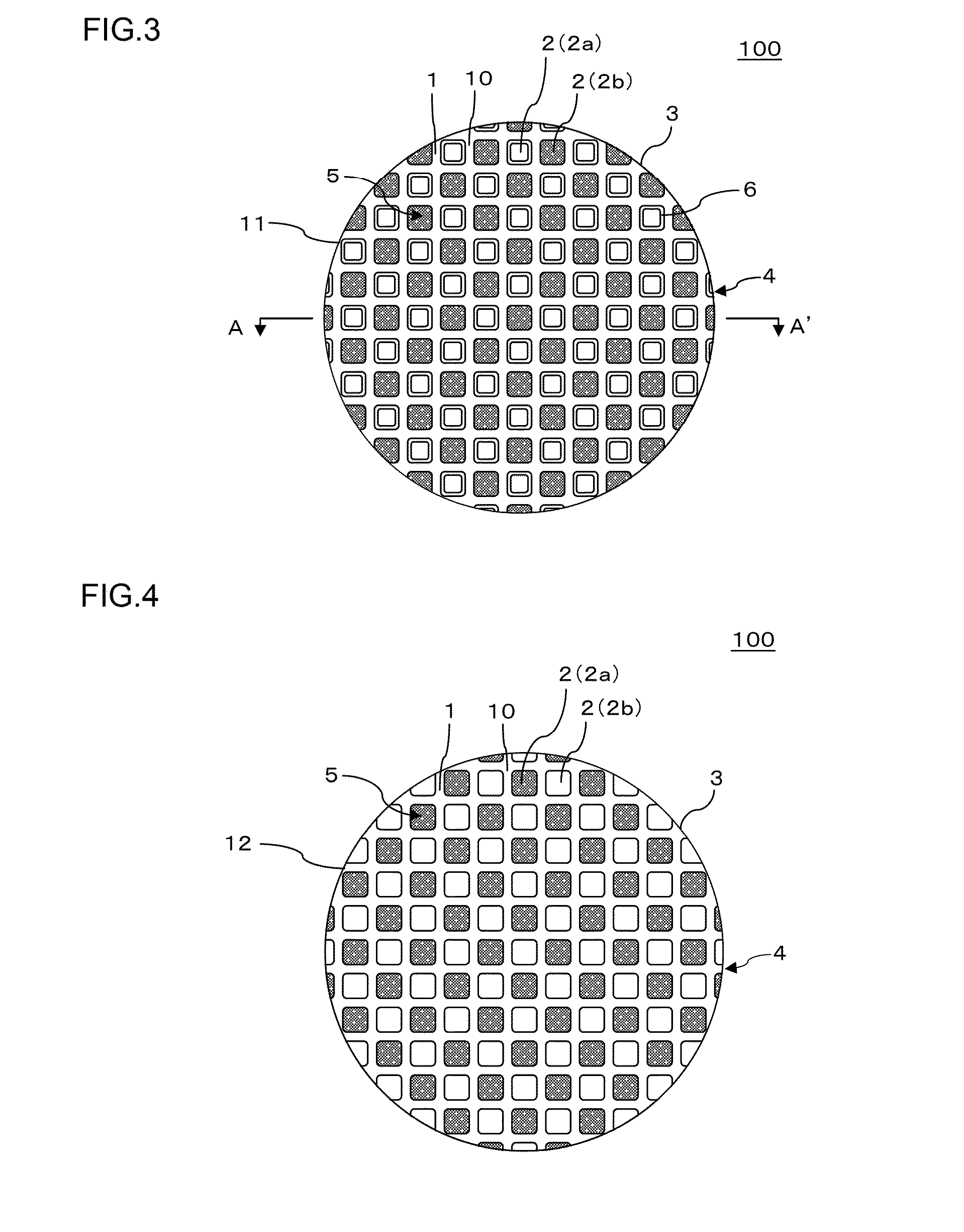
A method for manufacturing a plugged honeycomb structure, includes: a forming raw material preparation step of mixing and kneading a partition wall base material raw material at least including cordierite powder and binder with water to obtain a partition wall base material forming raw material; a forming / drying step of forming the partition wall base material forming raw material to obtain a honeycomb formed body, and drying the honeycomb formed body to obtain a honeycomb dried body; a slurry application step of applying trapping layer forming slurry including a cordierite forming raw material or alumina to a surface of a not-fired partition wall base material of the obtained honeycomb dried body; a firing step of firing the slurry-applied honeycomb dried body; and a plugging step of disposing a plugging portion at open ends of predetermined cells of the slurry-applied honeycomb dried body or of the honeycomb fired body.

Description

[0001]The present application is an application based on JP 2015-058570 filed on Mar. 20, 2015 with Japan Patent Office, the entire contents of which are incorporated herein by reference.BACKGROUND OF THE INVENTION[0002]1. Field of the Invention[0003]The present invention relates to methods for manufacturing a plugged honeycomb structure and plugged honeycomb structures. More particularly the present invention relates to a method for manufacturing a plugged honeycomb structure capable of manufacturing a plugged honeycomb structure with suppressed densification of a trapping layer, high heat capacity, low initial pressure loss, small increase in pressure loss during the deposition of particulate matter, and high trapping efficiency of particulate matter, and relates to a plugged honeycomb structure manufactured by such a manufacturing method.[0004]2. Description of the Related Art[0005]Gas emitted from an internal combustion engine, such as a diesel engine, or various types of combus...

Claims


Application Information

Patent Timeline
IPC IPC(8): C04B38/00C04B35/195C04B35/46C04B35/505C04B35/64C04B35/48
CPCC04B38/0012C04B35/64C04B35/195C04B35/46C04B35/505C04B35/48C04B35/117C04B38/0006C04B38/0009C04B2111/00793C04B2111/0081C04B2235/3206C04B2235/3217C04B2235/3225C04B2235/3229C04B2235/3232C04B2235/3244C04B2235/3418C04B2235/3445C04B38/0054C04B38/0074
Inventor KIKUCHI, YOSHIOKIMATA, TAKAFUMI
Owner NGK INSULATORS LTD
Learn More