
Method for manufacturing a plate-type heat pipe

a technology of heat pipe and plate, which is applied in the direction of indirect heat exchangers, semiconductor/solid-state device details, lighting and heating apparatus, etc., can solve the problems of high fabrication cost of plate-type heat pipes, the need for a long cooling period for the welding connection of the top plate and the base plate,

Inactive Publication Date: 2010-04-01
HON HAI PRECISION IND CO LTD
View PDF13 Cites 2 Cited by
  • Summary
  • Abstract
  • Description
  • Claims
  • Application Information

AI Technical Summary

Benefits of technology

[0006]A method for manufacturing a plate-type heat pipe includes the steps of: offering a top plate, a base plate, a wick structure adhered to the base plate; securing the top plate onto the base plate to make the top plate contact with the base plate; offering a microwave oven which includes a cover and a heating member located at a center portion of the cover, the cover defining an opening at a side thereof to allow microwave to enter the cover, the heating member defining a chamber; putting the secured top and base plates into the chamber of the heating member and turning on the microwave oven to make the microwave produced by the microwave oven enter the cover, the heating member absorbing the microwave and transforming the microwave to heat energy to heat the plate-type heat pipe whereby the base and top plates are heated and hermetically assembled together.

Problems solved by technology

On the other hand, the welding connection of the top plate and the base plate requires a quite long period to be cooled.
Thus, the production cycle of the plate-type heat pipe is long, whereby the fabrication cost of the plate-type heat pipe is high.

Method used


Image

  • Method for manufacturing a plate-type heat pipe
  • Method for manufacturing a plate-type heat pipe
  • Method for manufacturing a plate-type heat pipe

Examples


Embodiment Construction

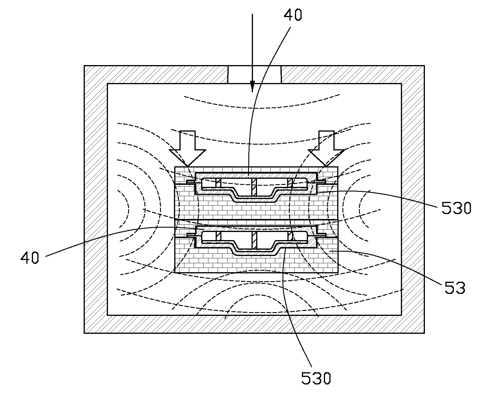
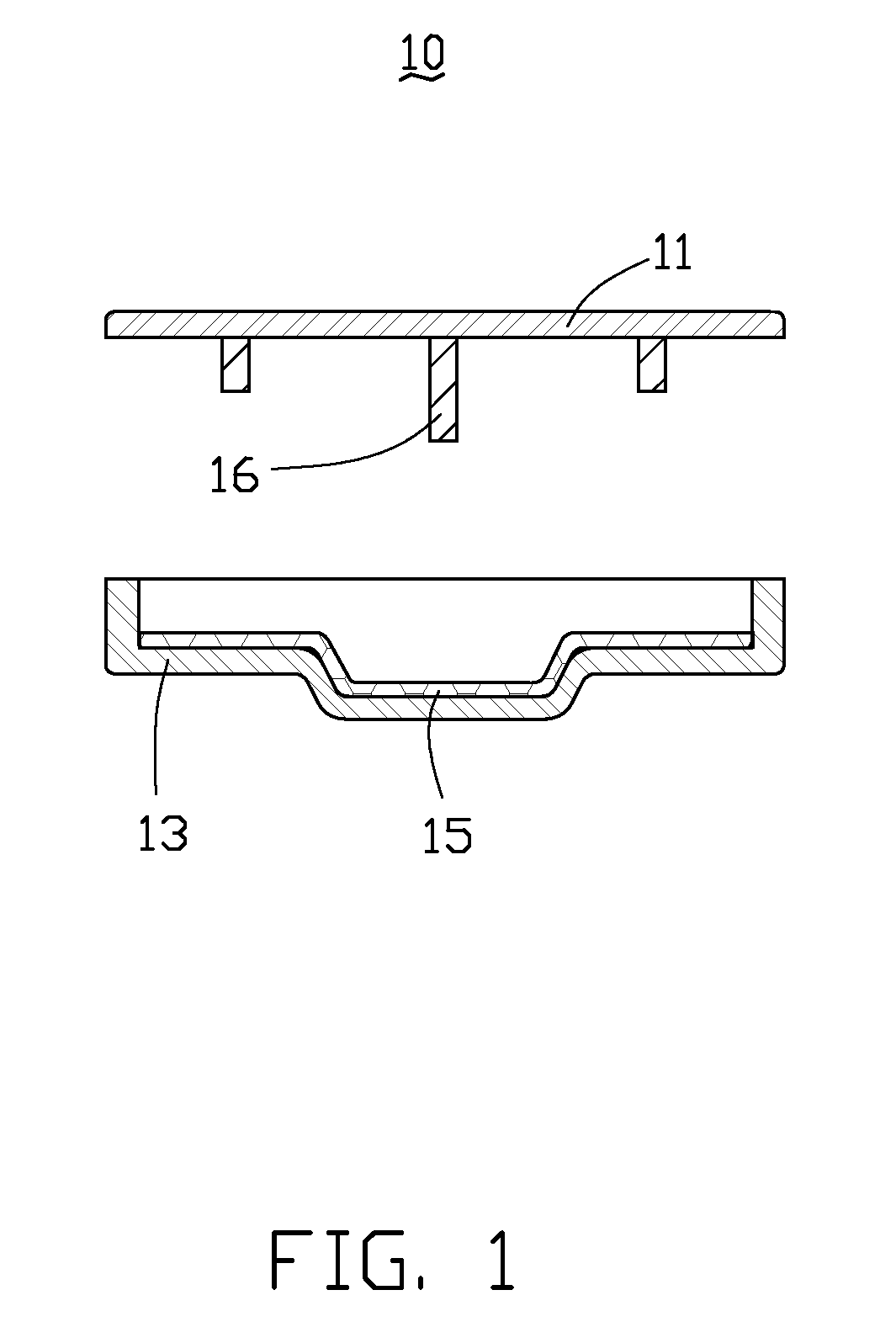
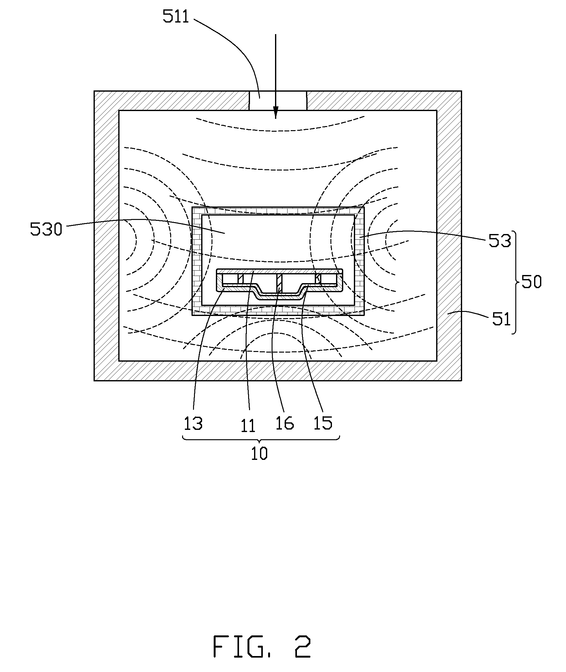
[0014]Referring to FIGS. 1-2, a method for manufacturing a plate-type heat pipe 10 in accordance with a first embodiment of the present invention comprises the steps of: 1) offering an elongated top plate 11, a bended base plate 13 engaging with the top plate 11, a wick structure 15 securely adhered to a top surface of the base plate 13, and a plurality of supporting poles 16 mounted on a bottom surface of the top plate 11; 2) securing the top plate 11 onto the base plate 13, in this state, the bottom surface of the top plate 11 contacting with a top surface of a periphery of the base plate 13, the supporting poles 16 abutting against a top surface of the wick structure 15; 3) offering a microwave oven 50, the microwave oven 50 comprising a cubical metal cover 51 and a cubical heating member 53 located at a center portion of the cover 51, the cover 51 defining an opening 511 at a side thereof to allow microwave to enter the cover 51, the heating member 53 defining a chamber 530 to r...


PUM

PropertyMeasurementUnit
dielectric constantaaaaaaaaaa
heat energyaaaaaaaaaa
dielectric constantaaaaaaaaaa

Abstract

A method for manufacturing a plate-type heat pipe includes the steps of: offering a top plate, a base plate, a wick structure adhered to the base plate; securing the top plate onto the base plate to make the top plate contact with the base plate; offering a microwave oven which includes a cover and a heating member located at a center portion of the cover, the cover defining an opening at a side thereof to allow microwave to enter the cover, the heating member defining a chamber; putting the secured top and base plates into the chamber of the heating member and turning on the microwave oven to make the microwave produced by the microwave oven enter the cover, the heating member absorbing the microwave and transforming the microwave to heat energy to heat the plate-type heat pipe, whereby the base and top plates are heated and hermetically assembled together.

Description

BACKGROUND OF THE INVENTION[0001]1. Field of the Invention[0002]The present invention relates to a method for manufacturing a plate-type heat pipe, and more particularly to a method for manufacturing a plate-type heat pipe having a good hermeticity.[0003]2. Description of Related Art[0004]Generally, plate-type heat pipes efficiently dissipate heat from heat-generating components such as a central processing unit (CPU) of a computer. A conventional plate-type heat pipe comprises a top plate, a base plate engaging with the top plate, and a wick structure formed on the base plate. The top plate and the base plate are assembled together by welding. When heat generated by a heat-generating component is inputted into the plate-type heat pipe via its heat absorbing portion, working fluid contained in the wick structure on the heat absorbing portion absorbs the heat and turns into vapor. The vapor presses joins of the top plate and the base plate and may leak out of the plate-type heat pipe...

Claims


Application Information

Patent Timeline
Patent Type & Authority Applications(United States)
IPC IPC(8): B23P15/26
CPCB23P15/26B23P2700/09F28D15/0233F28D15/046Y10T29/49366H01L23/427H01L2924/0002F28F2275/064H01L2924/00
Inventor HOU, CHUEN-SHU
Owner HON HAI PRECISION IND CO LTD
Learn More