Tire state estimator and tire state estimation method

a tire state and tire technology, applied in vehicle tyre testing, instruments, roads, etc., can solve the problems of unstable vehicle dynamic behavior and driver discomfort, and achieve the effect of reducing the angle of steering wheel

Inactive Publication Date: 2010-04-01
NISSAN MOTOR CO LTD +1
View PDF5 Cites 28 Cited by
  • Summary
  • Abstract
  • Description
  • Claims
  • Application Information

AI Technical Summary

Benefits of technology

[0004]In general, when a tire is steered, the lateral force and self aligning torque of the tire change with delay due to elastic deformation of the tire. Accordingly, the actual grip degree of the tire changes with delay with respect to the steer angle of the tire. Situations are possible in which when the steer angle of the tire has increased and reached a value that is, in steady state, corresponding to an upper limit of grip, the actual grip degree has not yet reached the upper limit. If the tire grip degree estimator of JP2005-8062 is employed to create a control system for preventing a tire set from shifting from grip state to slip state, the control system may permit a situation in which the steer angle and slip angle of the tire overshoot values that are, in steady state, corresponding to the upper limit, in consideration that an estimated tire grip degree is still below the upper limit. This may make the dynamic behavior of the vehicle unstable. Moreover, in response to delayed detection of the overshoot, the steering wheel angle may be reduced excessively due to the delay of response of grip degree to steering wheel angle. This may cause a phenomena of hunching between grip state and slip state, and thereby make a driver uncomfortable.

Problems solved by technology

This may make the dynamic behavior of the vehicle unstable.
This may cause a phenomena of hunching between grip state and slip state, and thereby make a driver uncomfortable.

Method used


Image

  • Tire state estimator and tire state estimation method
  • Tire state estimator and tire state estimation method
  • Tire state estimator and tire state estimation method

Examples


second embodiment

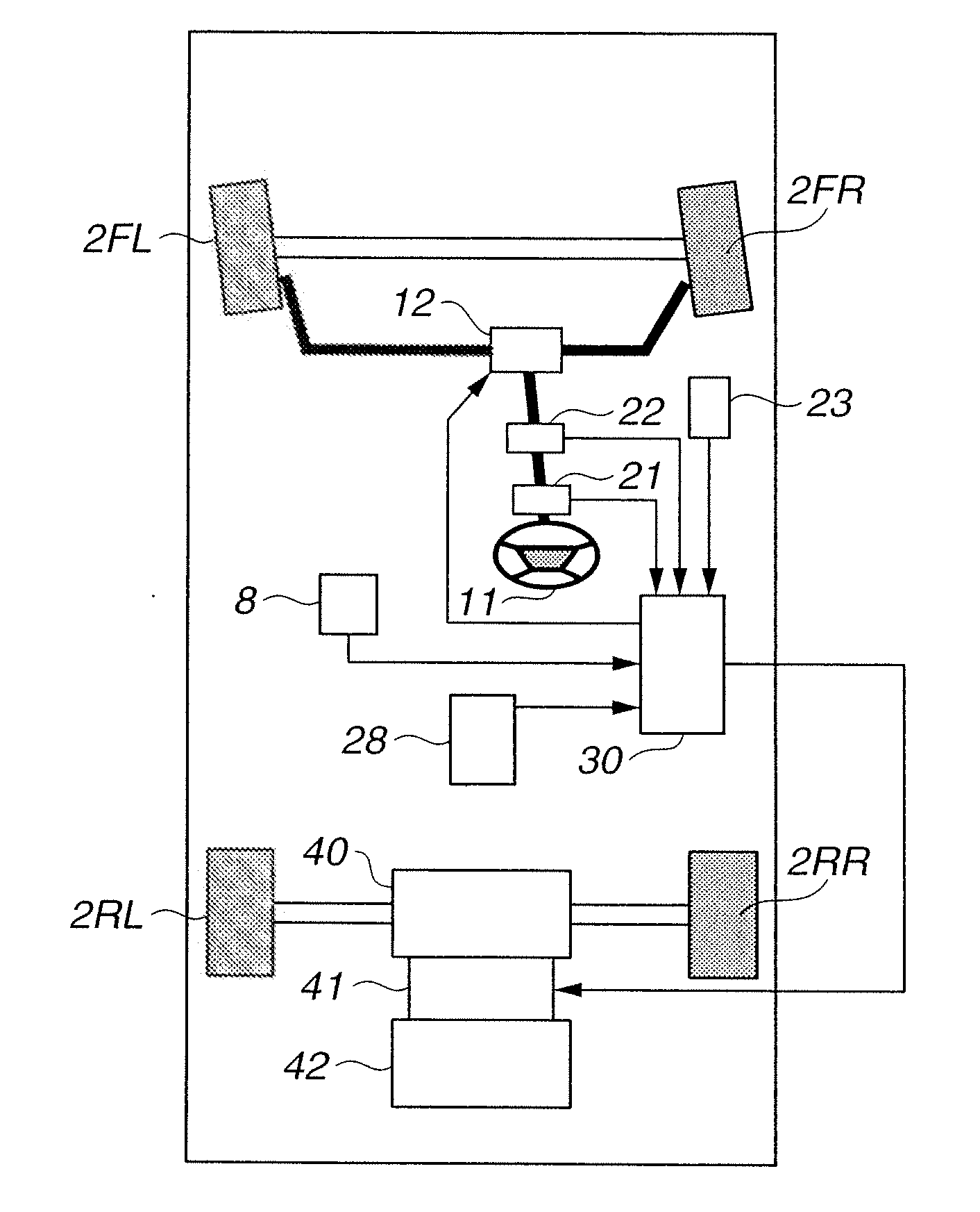
[0142]As in the second embodiment, integrated controller 30 is configured to receive input of accelerator opening APO measured by accelerator pedal sensor 23, steering wheel angle STR measured by steering wheel angle sensor 21, steering motor torque τact and front tire steer angle θf measured by steering motor 13, vehicle yaw rate γ measured by yaw rate sensor 8, vehicle longitudinal acceleration ax and vehicle lateral acceleration ay measured by acceleration sensor 28, and wheel speeds ωFL, ωFR, ωRL and ωRR measured by the rotational speed sensors.

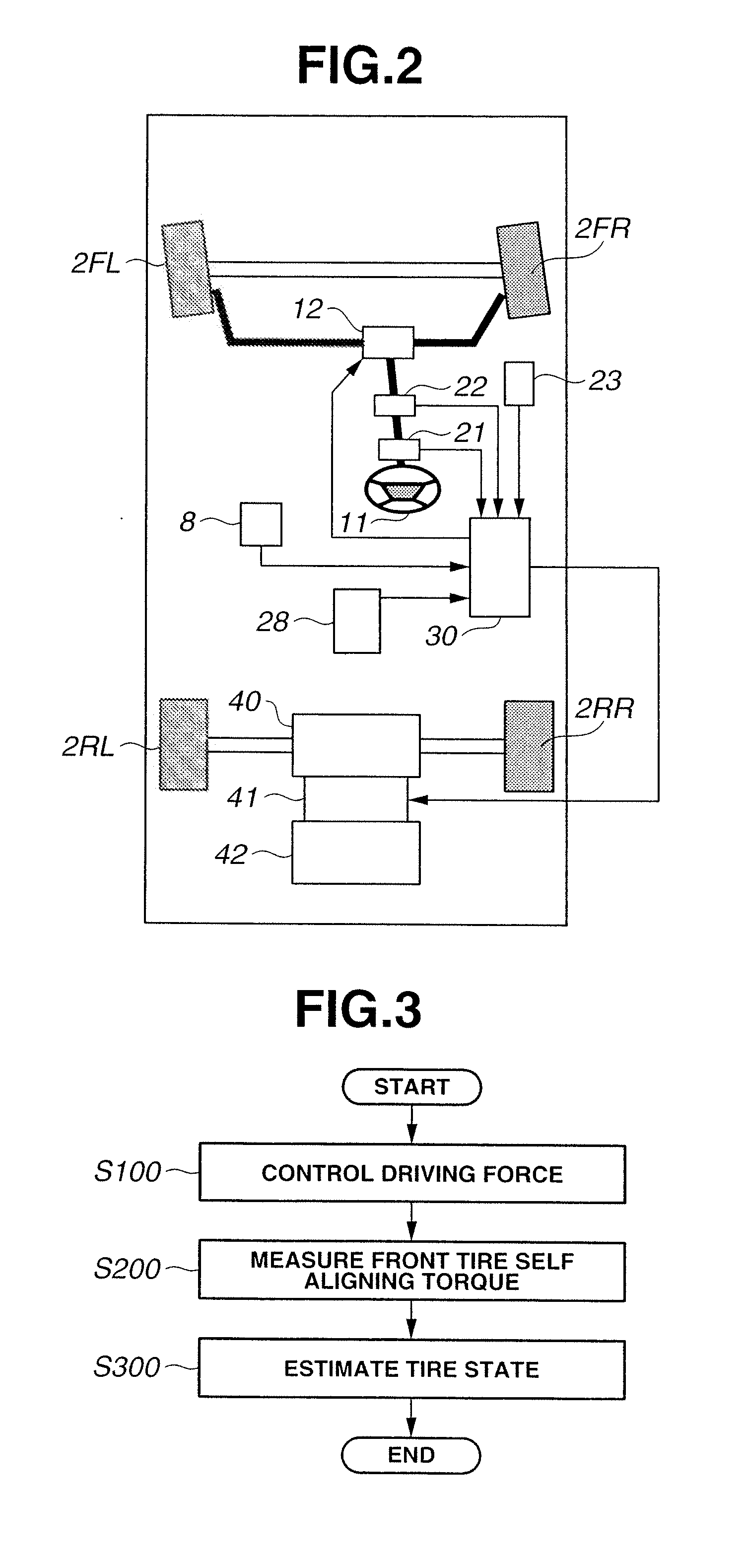
[0143]Integrated controller 30 performs the process of FIG. 3 as in the first and second embodiments, where Step S100 is the same as in the first and second embodiments, Step S200 is the same as in the second embodiment, but detailed contents of Step S300 are different from those in the first and second embodiments.

[0144]At Step S300, integrated controller 30 carries out a system of tire state estimation shown in FIG. 7. In the configurat...

first embodiment

[0157]As in the first embodiment, in consideration that equation (3) defines the relationship among estimated lateral force upper limit Fymax, tire-road friction coefficient μ, and tire vertical load Fz, and μ and Fz appear in the form of μFz in equations (27) and (28), μFz is calculated as Fymax on a basis of front tire self aligning torque τaf, estimated front tire slip angle αfhat and front tire slip ratio σf, using equations (27) and (28).

[0158]Equations (27) and (28) are somewhat complicated and include bifurcation. Accordingly, equations (27) and (28) are solved by an iterative calculation method such as the Newton method so as to find a value of μFz with which a value of equation (27) or (28) conforms to measured front tire self aligning torque τaf. Since situations are possible in which two valid values of μFz exist with respect to a single self aligning torque as shown in FIG. 8, a first iterative calculation process is started with μFz set to an initial value of 0, and a s...

third embodiment

[0188]First, left and right front tire slip ratios σfl and σfr are calculated on a basis of left and right front wheel speeds ωFL and ωFR, using equation (23) shown in the

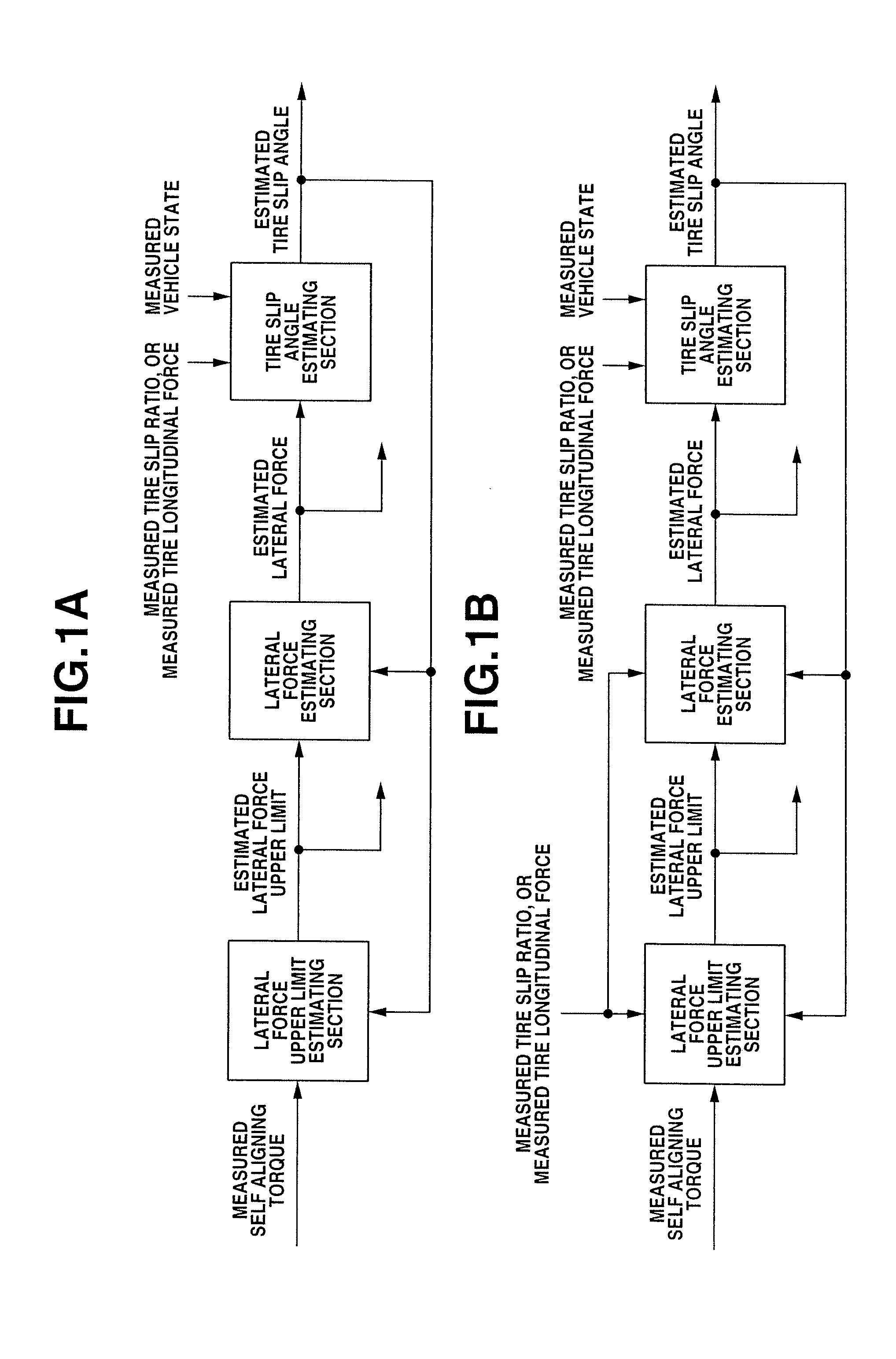
[0189]In FIG. 10, lateral force upper limit estimating section 102 estimates left and right front tire lateral force upper limits Fyflmax and Fyfrmax on a basis of the measured left and right front tire self aligning torques calculated at Step S200, the estimated left and right front tire slip angles αflhat and αfrhat outputted by tire slip angle estimating section 302, and the measured left and right front tire slip ratios σfl and σfr or measured left and right front tire longitudinal forces Fxfl and Fxfr, using the method shown in the third embodiment.

[0190]Lateral force estimating section 202 calculates estimated left and right front tire lateral forces Fyflhat and Fyfrhat on a basis of the estimated left and right front tire lateral force upper limits Fyflmax and Fyfrmax outputted by lateral force upper limit e...


PUM


Abstract

A tire state estimator includes a lateral force upper limit estimating section, a lateral force estimating section, and a tire slip angle estimating section. The lateral force upper limit estimating section calculates an estimated tire lateral force upper limit, on a basis of an estimated tire slip angle and a measured tire self aligning torque. The lateral force estimating section calculates an estimated tire lateral force, on a basis of the estimated tire lateral force upper limit calculated by the lateral force upper limit estimating section and the estimated tire slip angle. The tire slip angle estimating section calculates the estimated tire slip angle, on a basis of the estimated tire lateral force calculated by the lateral force estimating section and a measured vehicle state.

Description

BACKGROUND OF THE INVENTION[0001]The present invention relates generally to automotive vehicles, and particularly to tire state estimators and tire state estimation methods for estimating a state of a tire set of an automotive vehicle.[0002]Japanese Patent Application Publication No. 2005-8062 (JP2005-8062) discloses a tire grip degree estimator for estimating a degree of grip of a tire set of an automotive vehicle in a lateral direction of the tire set. The estimation is implemented by calculating an estimated tire grip degree on a basis of a ratio of an estimated tire self aligning torque to a modeled tire self aligning torque.[0003]Self aligning torque (SAT) is a torque that is applied from a road surface to a steerable tire about the axis of steering.SUMMARY OF THE INVENTION[0004]In general, when a tire is steered, the lateral force and self aligning torque of the tire change with delay due to elastic deformation of the tire. Accordingly, the actual grip degree of the tire chang...

Claims


Application Information

Patent Timeline
Patent Type & Authority Applications(United States)
IPC IPC(8): G01M17/02
CPCG01M17/02B60W40/101
Inventor JOE, SHINICHIRODEGUCHI, YOSHITAKAHSU, YUNG-HSIANG JUDYLAWS, SHAD MITCHELLGERDES, JOSEPH CHRISTIAN
Owner NISSAN MOTOR CO LTD
Why Eureka
Try Eureka