Check patentability & draft patents in minutes with Patsnap Eureka AI!

Dynamic Barcode System

a barcode and dynamic technology, applied in the field of barcode displays and scanners, can solve the problem that printed barcodes cannot be used to transfer data subject to chang

Inactive Publication Date: 2010-04-01
UNITED STATES OF AMERICA THE AS REPRESENTED BY THE SEC OF THE ARMY
View PDF18 Cites 30 Cited by
  • Summary
  • Abstract
  • Description
  • Claims
  • Application Information

AI Technical Summary

Benefits of technology

[0010]Accordingly, one object of the present invention is to provide a barcode data transfer system which can operate on low power when transferring dynamic information.
[0011]Yet another object of the present invention is to provide a system in which dynamic barcode information can be retrieved in virtually any setting or location.
[0014]In one embodiment of the present invention, the barcode reader has an associated transmitter for purposes of transmitting an infrared (IR) signal or equivalent signal to a receiver associated with the microprocessor and display. The receiver then sends a signal to the microprocessor to retrieve desired information to be sent to the display for readout by the barcode reader. The microprocessor has memory and processing circuitry for storing and processing information detected by the sensor. The IR link between the barcode reader and display / processor unit allows for a two-way transfer of data or commands to be used for the transfer of dynamic information.

Problems solved by technology

By their nature, printed barcodes cannot be used to transfer data that is subject to change.
These reasons include safety concerns, power requirements, regulatory concerns, and location constraints which preclude the use of such traditional links.

Method used


Image

  • Dynamic Barcode System
  • Dynamic Barcode System
  • Dynamic Barcode System

Examples


Embodiment Construction

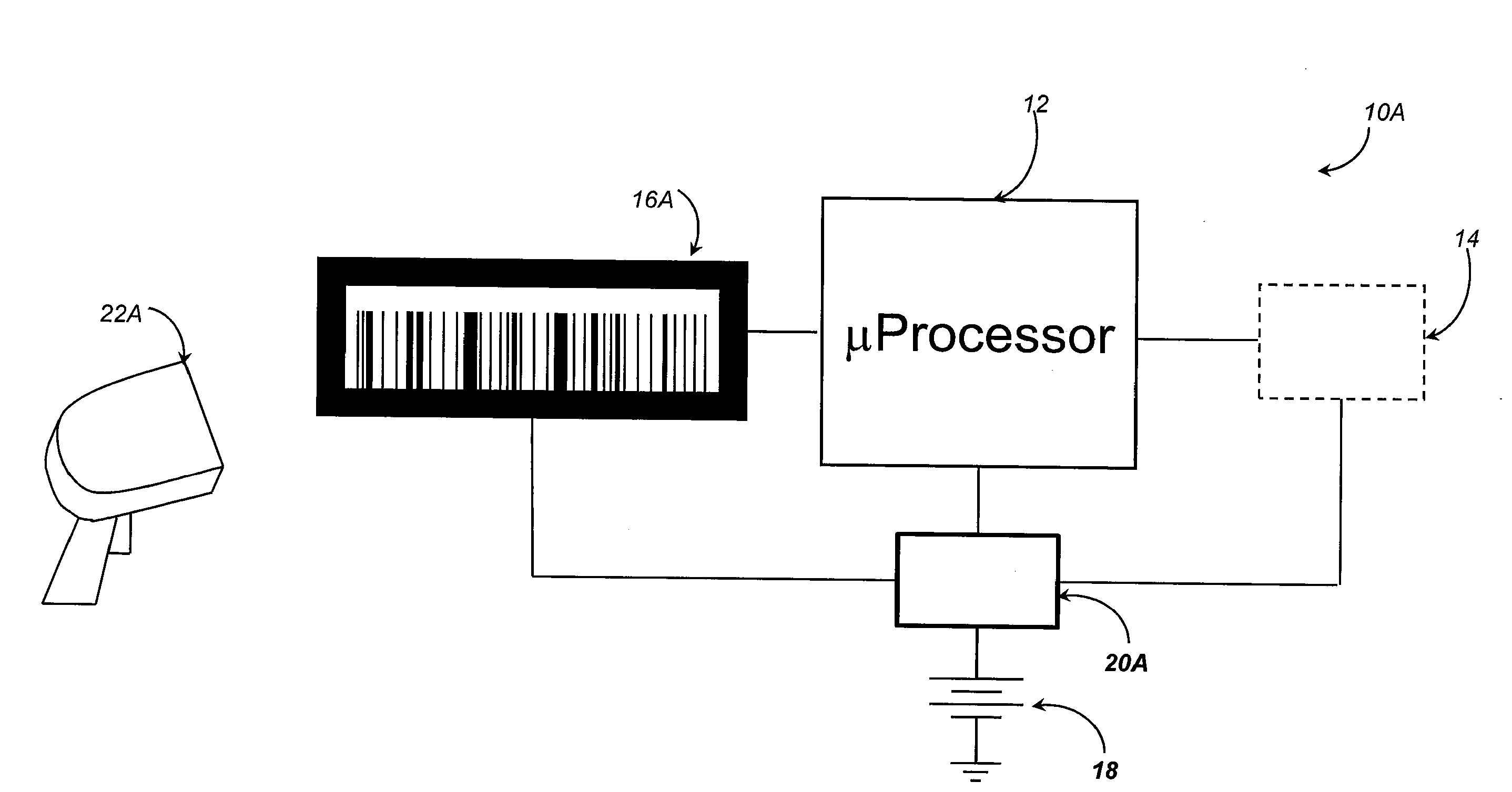
[0023]With reference to FIG. 1, a dynamic barcode system 10A according to the present invention includes a microprocessor 12 connected to a signal generator 14 which could, for example, be a notional set of sensors (e.g., sensors which measure temperature, humidity, wind speed, shock, chemical emissions, time in transit, barometric pressure, etc.). Microprocessor 12, signal generator 14, and display 16A receive power from battery 18 through power conditioning circuitry 20A.

[0024]The microprocessor 12 logs data from the signal generator 14 and drives a display 16A, e.g., a liquid crystal display (LCD) or equivalent display. A microprocessor appropriate for this application is the Texas Instrument MSP430 microprocessor family or equivalent. From the data collected from the signal generator 14, the microprocessor generates barcodes which are transmitted to the display 16A. A barcode reader 22A is used to read the display. Barcode reader 22A is a battery-powered barcode reader of a type...


PUM


Abstract

A dynamic barcode system includes a microprocessor connected to a sensor or group of sensors. The microprocessor connects to a barcode display. Data collected by the sensor or group of sensors is processed by the microprocessor and sent to the barcode display. A barcode reader reads the barcode display. The barcode display, microprocessor and group of sensors are arranged on a packet which is attachable to a specimen to be monitored. The barcode reader has an infrared transmitter for sending a signal to an infrared receiver associated with the barcode display. The infrared receiver upon receiving a signal from the barcode reader sends a signal to the microprocessor requesting that the microprocessor send requested data for viewing on the barcode display. The displayed barcode is then read by the barcode reader. In such a manner, continually changing data collected by the sensors can be stored and retrieved as desired.

Description

DEDICATORY CLAUSE[0001]The invention described herein may be manufactured, used and licensed by or for the U.S. Government for governmental purposes without payment of any royalties to the inventor or to any subsequent assignees.BACKGROUND OF THE INVENTION[0002]I. Field of the Invention[0003]The present invention pertains to barcode displays and scanners.[0004]More particularly the present invention pertains to a barcode display and reader which can be used to transfer dynamic information.[0005]II. Discussion of the Background[0006]Barcodes present a well-developed way of allowing a user to retrieve data on some item. This data can be very simple, like a UPC code, or it can be more complex, like the routing information on a package. New barcodes, such as the various two-dimensional barcodes, allow for a relatively dense storage of readable data. In some cases, this can be the equivalent of several thousand bits per square inch.[0007]The technology for generating and reading barcodes...

Claims


Application Information

Patent Timeline
Patent Type & Authority Applications(United States)
IPC IPC(8): G06K7/10
CPCG06K7/1095G06K7/10881
Inventor BRADFORD, GLENN PATTON
Owner UNITED STATES OF AMERICA THE AS REPRESENTED BY THE SEC OF THE ARMY
Features
  • R&D
  • Intellectual Property
  • Life Sciences
  • Materials
  • Tech Scout
  • Unparalleled Data Quality
  • Higher Quality Content
  • 60% Fewer Hallucinations
Learn More