Radiation detecting apparatus and radiation image capturing system

a radiation image and detector technology, applied in liquid/fluent solid measurement, instruments, machines/engines, etc., can solve the problems of noise with respect to radiation image information, the irradiated surface (image-capturing surface) of the radiation conversion panel cannot be kept flat with respect to the subject, and the flexible radiation detector or radiation detector of the proposed radiation detecting apparatus cannot be easily placed in storage, etc., to achieve the effect of easy storag

Active Publication Date: 2010-04-01
FUJIFILM CORP
View PDF8 Cites 15 Cited by
  • Summary
  • Abstract
  • Description
  • Claims
  • Application Information

AI Technical Summary

Benefits of technology

[0014]A first object of the present invention is to enable a flexible radiation conversion panel to be kept in storage with ease when it is not being used to capture a radiation image of a subject. Further, the radiation conversion panel is capable of keeping its image-capturing surface flat with respect to a subject when it is used to capture a radiation image of the subject.

Problems solved by technology

However, the flexible radiation detector or radiation conversion panel of the proposed radiation detecting apparatus cannot easily be placed in storage during periods when it is not used to detect radiation having passed through a subject, i.e., when it is not used to capture a radiation image of a subject.
On the other hand, when the flexible radiation conversion panel is used to detect radiation having passed through a subject, i.e., when it is used to capture a radiation image of the subject, the irradiated surface (image-capturing surface) of the radiation conversion panel cannot be kept flat with respect to the subject.
Therefore, a signal component of the electric signals, which corresponds to the external light, results in noise with respect to the radiation image information.
The disclosed cassette-type radiation detecting apparatus is rigid as a whole, and therefore cannot be matched to the surface shape of a patient to be imaged.
Further, the cassette-type radiation detecting apparatus is so heavy that it cannot be handled with ease.
However, since the disclosed radiation detecting apparatus includes drive circuits, which are disposed in a direction in which the radiation detecting apparatus itself is flexible, the radiation detecting apparatus is not sufficiently flexible.
Furthermore, the disclosed radiation detecting apparatus includes readout amplifiers, which tend to limit the flexibility thereof.

Method used


Image

  • Radiation detecting apparatus and radiation image capturing system
  • Radiation detecting apparatus and radiation image capturing system
  • Radiation detecting apparatus and radiation image capturing system

Examples


first embodiment

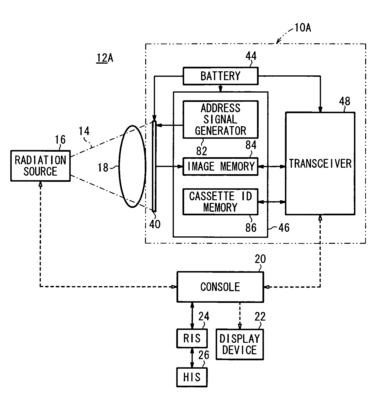
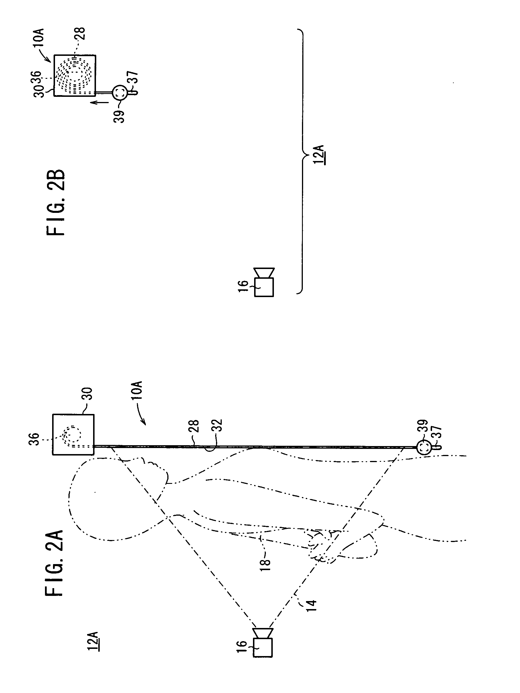
[0064]First, a radiation detecting apparatus (hereinafter also referred to as a “radiation detecting cassette”) 10A according to the present invention, and a radiation image capturing system 12A incorporating the radiation detecting apparatus 10A therein, will be described below with reference to FIGS. 1 through 9.

[0065]As shown in FIG. 1, the radiation image capturing system 12A according to the first embodiment of the present invention includes a radiation source 16 for irradiating a patient 18 as a subject with radiation 14 at a dose depending on image capturing conditions, a radiation detecting cassette 10A having a radiation detector or radiation conversion panel 40 for detecting radiation 14 that has passed through the patient 18, a display device 22 for displaying radiation image information based on the radiation 14 which has been detected by the radiation detector 40, and a console (controller) 20 for controlling the radiation detecting cassette 10A, the radiation source 16...

second embodiment

[0116]A radiation detecting apparatus 10B according to the present invention, and a radiation image capturing system 12B incorporating the radiation detecting apparatus 10B therein, will be described below with reference to FIGS. 10 through 15.

[0117]Those parts of the radiation detecting apparatus 10B and the radiation image capturing system 12B, which are identical to those of the radiation detecting apparatus 10A and the radiation image capturing system 12A (see FIGS. 1 through 9), are denoted by identical reference characters, and such features will not be described in detail below. This also holds true for the other embodiments.

[0118]The radiation detecting apparatus 10B and the radiation image capturing system 12B according to the second embodiment differ from the radiation detecting apparatus 10A and the radiation image capturing system 12A according to the first embodiment, in that a radiation detecting cassette 122B including the radiation detector (radiation conversion pane...

third embodiment

[0151]A radiation detecting apparatus 10C according to the present invention and a radiation image capturing system 12C incorporating the radiation detecting apparatus 10C will be described below with reference to FIGS. 16 through 19.

[0152]The radiation detecting apparatus 10C and the radiation image capturing system 12C according to the third embodiment differ from the radiation detecting apparatus 10B and the radiation image capturing system 12B according to the second embodiment (see FIGS. 10 through 15), in that a printed antenna (second antenna) 142 is printed on an electric insulation layer 140 on the rear surface 124b of the cassette storage pouch 120C. Also, a cable 144 from the transceiver 48 and a cable 146 connected to the printed antenna 142 are connected to each other by a connector 148 connected to the cable 144 and a connector 150 connected to the cable 146, for allowing signals to be sent and received between the wireless communication means 138 and the console 20 by...


PUM


Abstract

A radiation detecting apparatus includes a radiation conversion panel for detecting radiation that has passed through a subject and converting the detected radiation into radiation image information, and a casing for storing the radiation conversion panel as a roll when the subject is not being irradiated with radiation. When the subject is irradiated with radiation, the radiation conversion panel stored as a roll in the casing is unrolled and pulled out of the casing, and the radiation conversion panel is extended flatwise against the subject.

Description

CROSS-REFERENCE TO RELATED APPLICATION[0001]This application is based upon and claims the benefit of priority from Patent Application No. 2008-247102 filed on Sep. 26, 2008, in the Japan Patent Office, of which the contents are incorporated herein by reference.BACKGROUND OF THE INVENTION[0002]1. Field of the Invention[0003]The present invention relates to a radiation detecting apparatus for detecting radiation that has passed through a subject and converting the detected radiation into radiation image information, and a radiation image capturing system incorporating such a radiation detecting apparatus therein.[0004]2. Description of the Related Art[0005]In the medical field, there have widely been used radiation image capturing systems, which apply radiation to a subject and guide the radiation that has passed through the subject to a radiation conversion panel, which in turn captures a radiation image from such radiation. Known forms of radiation conversion panels include a conven...

Claims


Application Information

Patent Timeline
Patent Type & Authority Applications(United States)
IPC IPC(8): G01T1/24G01T1/20
CPCG01T1/00A61B6/4494A61B6/548
Inventor TSUBOTA, KEIJIOHTA, YASUNORINISHINO, NAOYUKIYOSHIDA, YUTAKAKITO, EIICHIIMAI, SHINJISETO, YASUHIRO
Owner FUJIFILM CORP
Why Eureka
Try Eureka