Planar transformer

a transformer and planar technology, applied in the direction of transformer/inductance details, inductance, variable inductance, etc., can solve the problems of additional time and cost, one inflexible aspect of such devices,

Inactive Publication Date: 2010-04-01
LINCOLN GLOBAL INC
View PDF11 Cites 25 Cited by
  • Summary
  • Abstract
  • Description
  • Claims
  • Application Information

AI Technical Summary

Benefits of technology

[0004]In one embodiment a planar transformer includes one or more sheets of dielectric material having individually formed electrically conductive traces that define magnetically coupled primary and secondary windings. First and second sets of connector ends extends from the one or more sheets of dielectric material, where the first and second sets of connector ends are connected to the primary and second windings respectively for electrical connection with associated circuitry. An auxiliary winding is formed on the one or more sheets of dielectric material and is magnetically coupled with the primary and / or secondary winding, wherein the auxiliary winding includes a third set of connector ends that is offset with respect to the first and second set of connector ends.

Problems solved by technology

Still, one inflexible aspect of such devices relates to the design of the turns ratio.
Whereas round wire wound onto a core provides a certain degree of design flexibility, new printed circuits must be fabricated for each coil pattern desired resulting in additional time and cost.

Method used


Image

  • Planar transformer
  • Planar transformer
  • Planar transformer

Examples


Embodiment Construction

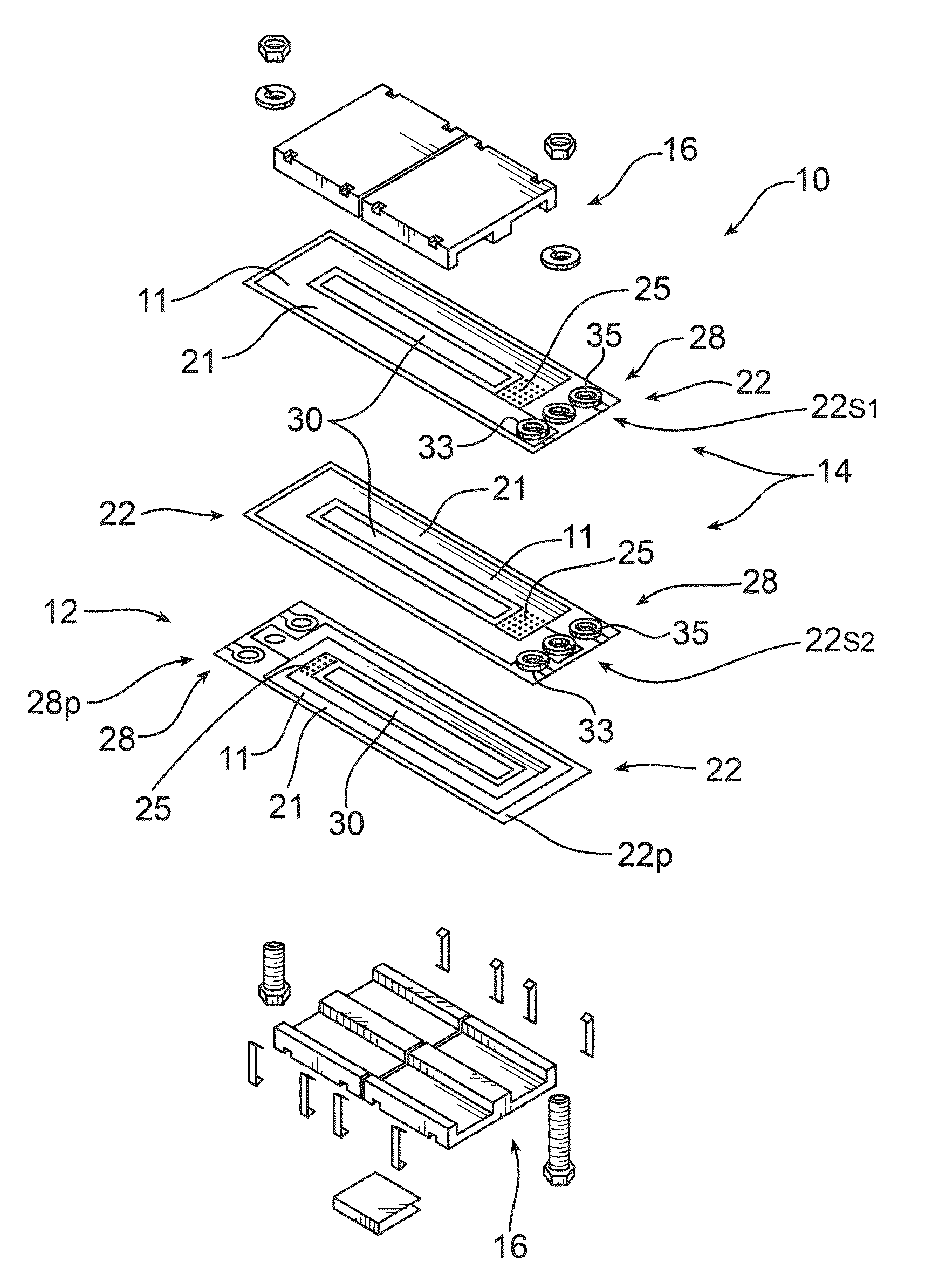
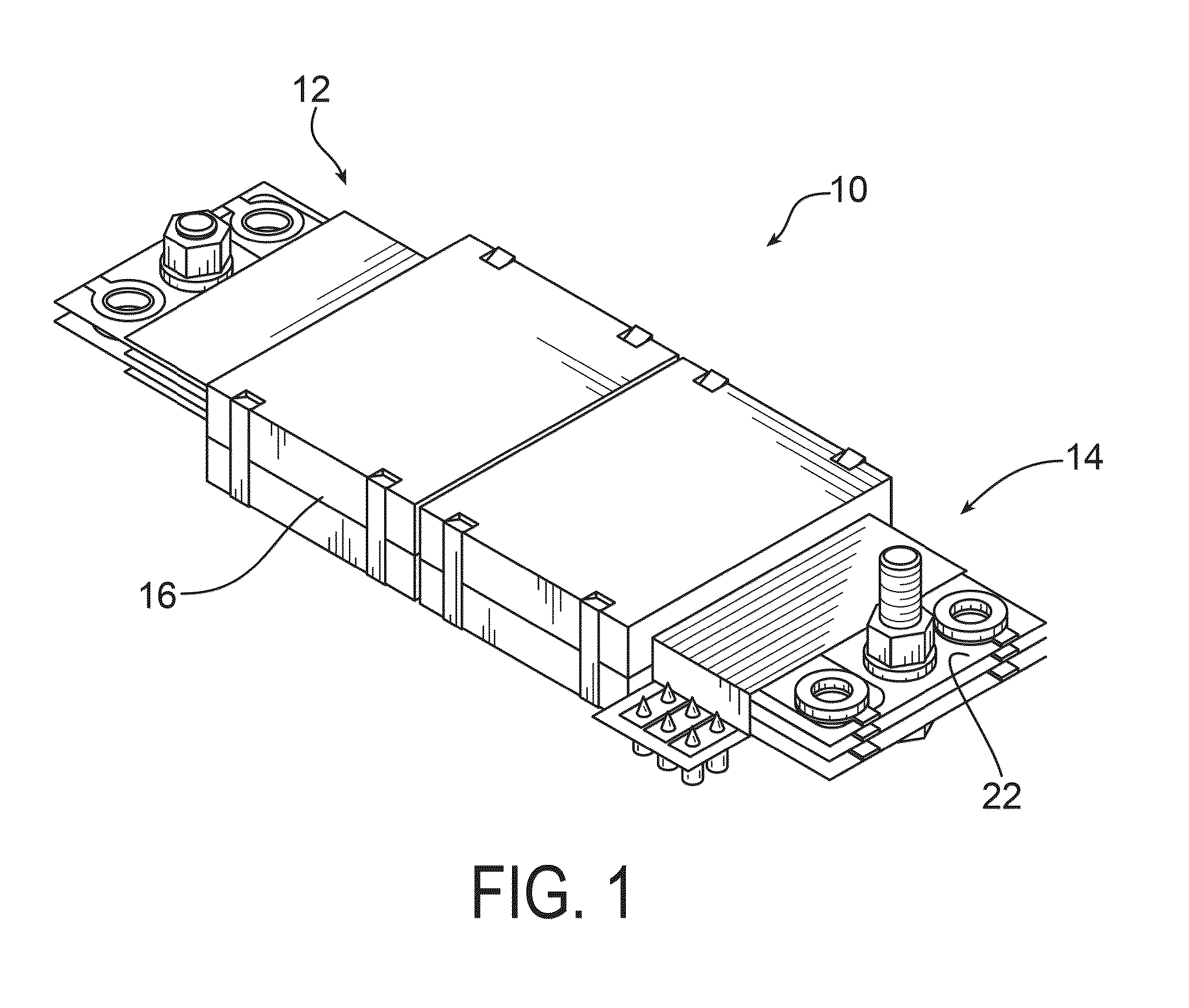
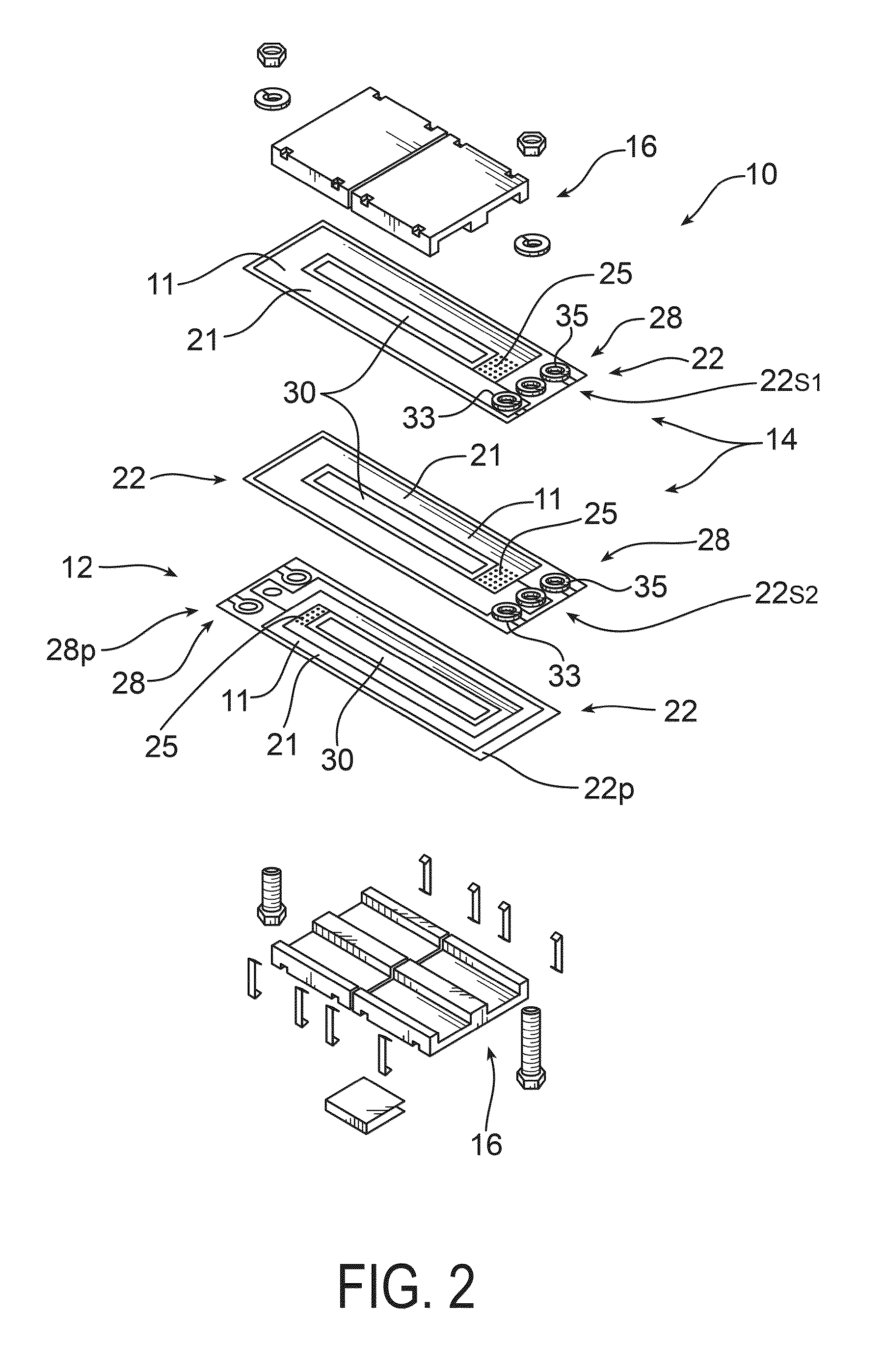
[0015]Referring now to the drawings wherein the showings are for purposes of illustrating embodiments of the invention only and not for purposes of limiting the same, FIG. 1 shows a transformer depicted generally at 10. The transformer 10 may be relatively compact and constructed for installation in applications having limited space, for example, as may be found on circuit boards used in machine control or other applications, not shown in the Figures. Examples of other applications may include power supplies, which may be switching power supplies, used in machinery like that of a welding machine. However, the transformer 10 of the embodiments of the subject invention may be utilized in any device or machine chosen with sound engineering judgment. Accordingly, the transformer 10 may be thin, compact and relatively light weight, herein referred to as a planar transformer 10, and may be mountable onto a circuit board or structural member by way of fasteners or other means.

[0016]Referri...


PUM

PropertyMeasurementUnit
thicknessaaaaaaaaaa
thicknessaaaaaaaaaa
thicknessaaaaaaaaaa

Abstract

A planar transformer includes first and second windings that may be comprised of electrically conductive traces etched onto one or more printed circuit boards. The printed circuit boards may be arranged in various orientations so as to change the turns ratio of the planar transformer. In one embodiment, the printed circuit boards are substantially similar and may be electrically connected via connectors that separate the circuit boards. Insulating sleeves may be inserted between the printed circuit boards in an interleaved configuration.

Description

[0001]This patent application is a continuation-in-part of patent application Ser. No. 12 / 238,492 filed on Sep. 26, 2008, which is incorporated herein by reference in its entirety.TECHNICAL FIELD[0002]The present invention pertains to electrical transformers, and more particularly, to planar transformers having a modular configuration.BACKGROUND OF THE INVENTION[0003]Planar transformers provide simplified solutions for compact electrical devices and have a generally planar form incorporating a larger number of coils as a printed circuit than can be fit into the equivalent space of round cross-sectional wire. Planar printed circuits afford many design options, one of which allows the coil to take any shape and width. Wide conductors make higher current flow possible. Thin conductors significantly reduce the transformer's weight. Still, one inflexible aspect of such devices relates to the design of the turns ratio. Whereas round wire wound onto a core provides a certain degree of desi...

Claims


Application Information

Patent Timeline
Patent Type & Authority Applications(United States)
IPC IPC(8): H01F5/00
CPCH01F27/2804H01F27/29H01F27/324H01F2027/2819H01F30/04H01F2027/2809H01F29/02
Inventor KOPRIVNAK, GEORGE BRADLEYWILLIAMS, THOMAS DAVID
Owner LINCOLN GLOBAL INC
Why Eureka
Try Eureka