Reference mark forming device and recording apparatus provided with the reference mark forming device

Inactive Publication Date: 2010-04-01
SEIKO EPSON CORP
View PDF2 Cites 6 Cited by
  • Summary
  • Abstract
  • Description
  • Claims
  • Application Information

AI Technical Summary

Benefits of technology

[0011]An advantage of some aspects of the invention is to improve the recording accuracy in the recording apparatus by synchronizing

Problems solved by technology

Therefore, when there arises a transport error caused by slippage between the transport belt and the recorded material, the dot formation timing by the recording head might be deviated from the actual transported positions of the recorded material.
Therefore, the related art disclosed in above-described JP-A-11-245383 might suffer from lowering of recording accuracy caused by the slippage between the transport belt and the recorded materia

Method used


Image

  • Reference mark forming device and recording apparatus provided with the reference mark forming device
  • Reference mark forming device and recording apparatus provided with the reference mark forming device
  • Reference mark forming device and recording apparatus provided with the reference mark forming device

Examples


first embodiment

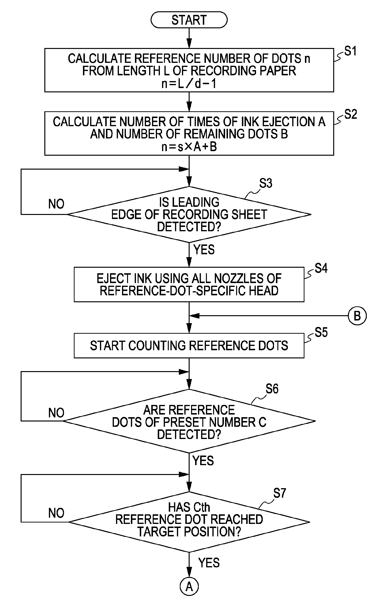
[0054]Referring now to FIG. 3 to FIG. 6, a first embodiment of the present invention will be described.

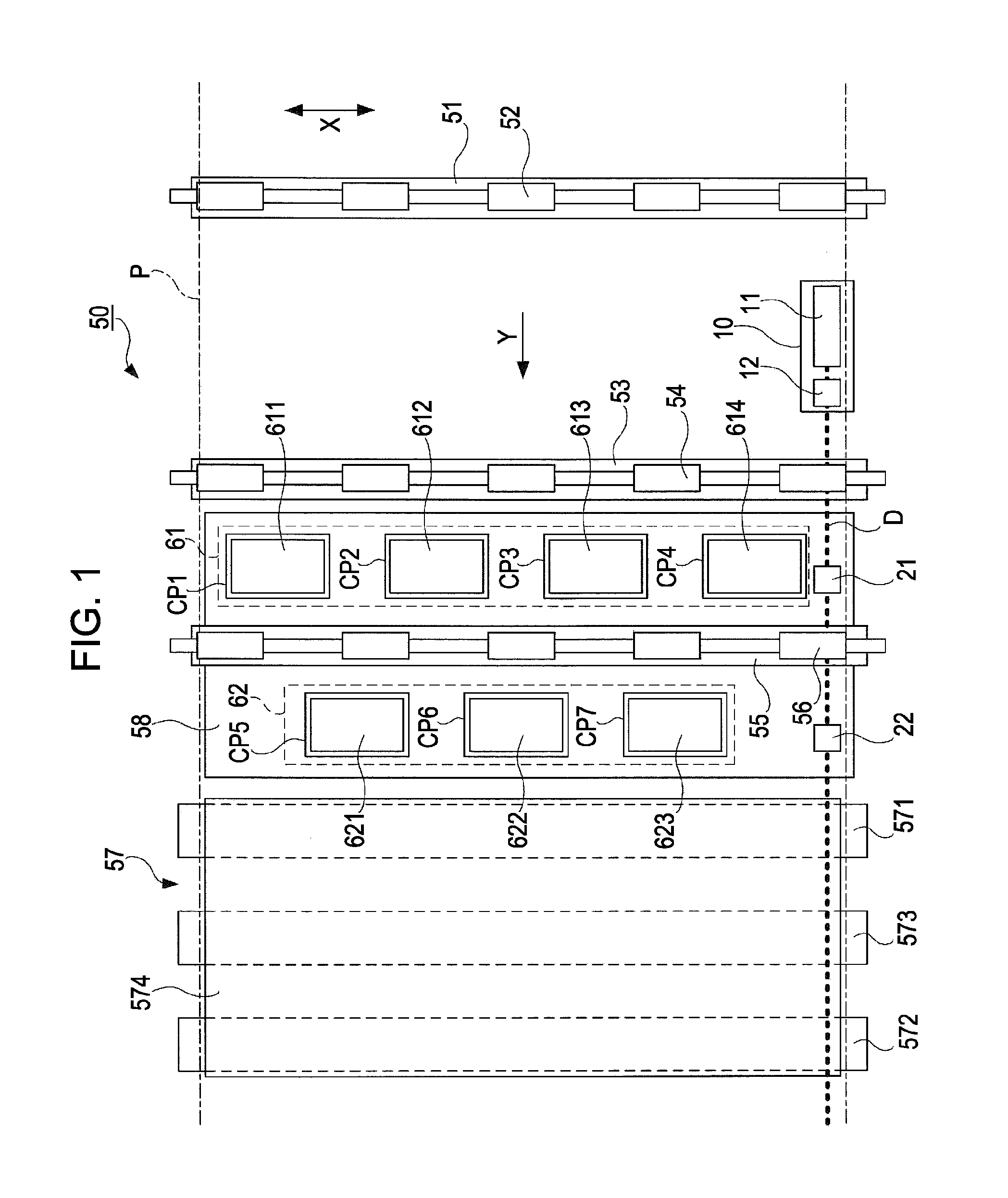
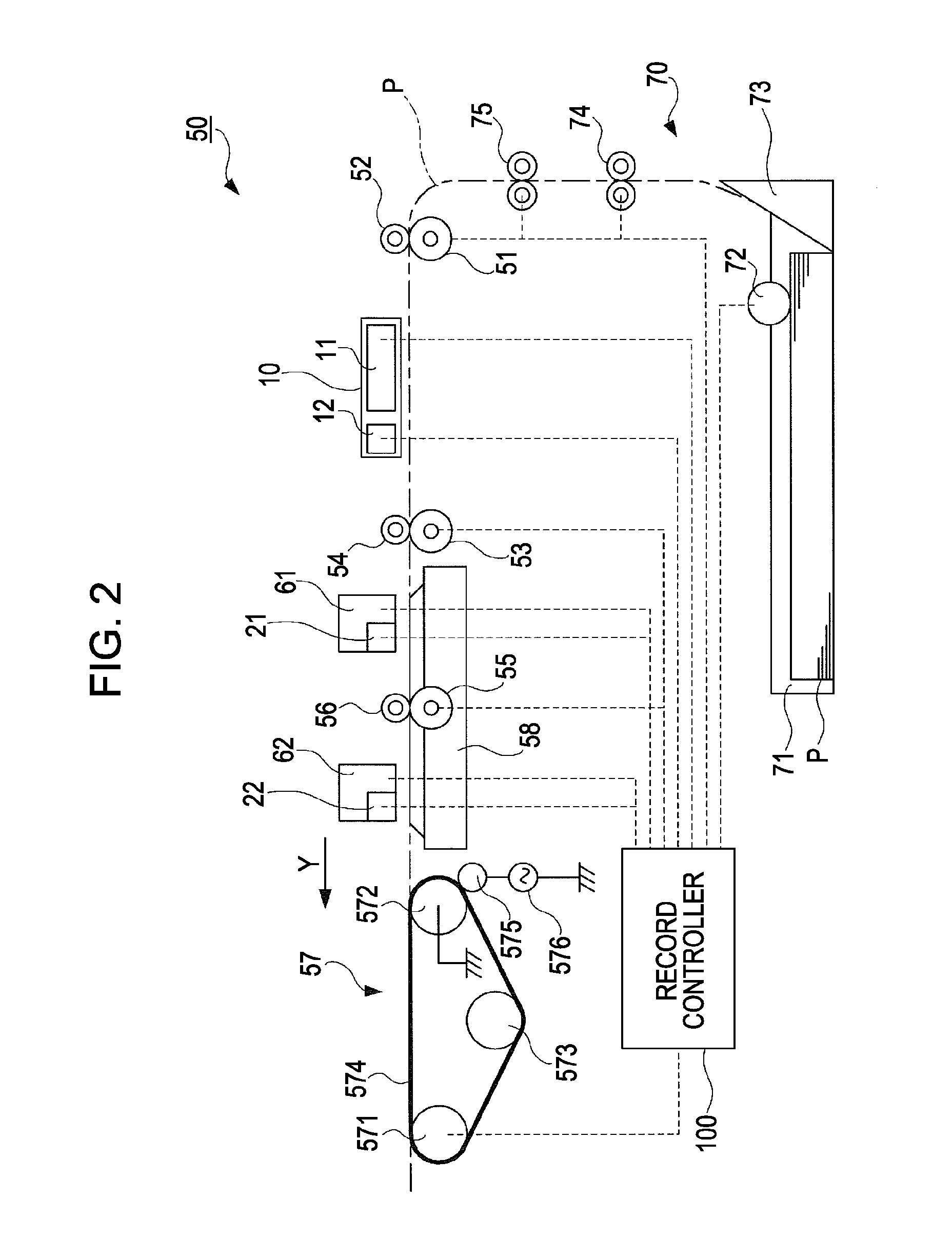
[0055]First of all, referring to FIG. 3, a configuration of the reference dot forming device 10 according to the embodiment of the present invention provided on the ink jet printer 50 will be described.

[0056]FIG. 3 is a block diagram showing the configuration of the reference dot forming device 10 according to the first embodiment.

[0057]The reference dot forming device 10 according to the embodiment of the invention includes a reference-dot-specific head 11 as a “reference-mark-specific head”, and a dot detection sensor 12 and a head drive unit 13 as “mark detection sensors”.

[0058]The reference-dot-specific head 11 forms the reference dots D by ejecting ink on the recording surface of the recording paper P transported in the transporting direction Y. The reference-dot-specific head 11 has eight ink ejecting nozzles N1 to N8 (mark forming elements) as dot forming elements disposed i...

second embodiment

[0082]Referring now to FIG. 7, a second embodiment will be described.

[0083]FIG. 7 is a plan view schematically showing a procedure for forming the reference dots D on the recording surface of the recording paper P according to the second embodiment.

[0084]In the reference dot forming device 10 in the second embodiment, the dot detection sensor 12 is arranged at a position farther from the reference-dot-specific head 11 than in the first embodiment. Also, the distance of the target position Y2 in the range of detection of the dot detection sensor 12 from the ink ejecting nozzle N1 is set to be at a distance corresponding to three times the nozzle pitch d. In addition, the reference dot forming device 10 in the second embodiment includes a leading edge position sensor 14 for detecting the position of the leading edge of the recording paper P in the transporting direction Y. The target position Y1 in the range of detection of the leading edge position sensor 14 is set in such a manner t...

third embodiment

[0091]Referring now to FIG. 8, a third embodiment will be described.

[0092]FIG. 8 is a block diagram showing the configuration of the reference dot forming device 10 according to the third embodiment.

[0093]The reference-dot-specific head 11 according to the third embodiment includes one ink ejecting nozzle N. In other words, the reference-dot-specific head 11 according to the third embodiment is different from the first embodiment and does not have the plurality of ink ejecting nozzles. In the reference-dot-specific head 11 according to the third embodiment, the output signals from the dot detection sensor 12 are entered directly to the head drive unit 13. In other words, in the reference dot forming device 10 according to the third embodiment, the head drive unit 13 is directly controlled by the output signals from the dot detection sensor 12.

[0094]Since the configurations other than those described above are the same as in the first embodiment, description will be omitted.

[0095]In ...


PUM


Abstract

A reference mark forming device configured to form reference marks on a recorded material to be transported in a predetermined transporting direction by a transporting device at a predetermined regular pitch in the transporting direction including: a reference-mark-specific head configured to form the reference marks on the recorded material transported by the transporting device; a mark detection sensor configured to detect the reference marks formed on the recorded material by the reference-mark-specific head on the downstream side of the reference-mark-specific head in terms of the transporting direction; and a head drive unit configured to drive the reference-mark-specific head on the basis of an output signal from the mark detection sensor, in which the reference-mark-specific head and the mark detection sensor are arranged so that the relative positional relation is maintained constant.

Description

BACKGROUND[0001]1. Technical Field[0002]The present invention relates to a reference mark forming device configured to form reference marks with a predetermined regular pitch in the transporting direction on a recorded material transported by a transporting device in a recording apparatus having the transporting device configured to transport the recorded material in the predetermined transporting direction and a recording head configured to form dots on a recording surface of the recorded material transported by the transporting device.[0003]2. Related Art[0004]As an example of a recording apparatus having a transporting device configured to transport a recorded material in a predetermined transporting direction and a recording head configured to form dots on a recording surface of the recorded material transported by the transporting apparatus, a line-head type ink jet recorder is publicly known. In the recording apparatus in this configuration, extremely high recording accuracy i...

Claims


Application Information

Patent Timeline
IPC IPC(8): B41J29/38
CPCB41J11/46
Inventor SUZUKI, TOSHIYUKI
Owner SEIKO EPSON CORP
Why Eureka
Try Eureka