Piezoelectric element, liquid ejecting head, and liquid ejecting apparatus

a technology of liquid ejecting head and piezoelectric element, which is applied in the direction of device details, device material selection, and device details, etc., can solve the problems of piezoelectric cracking, protective film having insufficient thickness at the edge (corner) of the upper surface, and damage to the upper electrode film. , to achieve the effect of improving durability

Inactive Publication Date: 2010-04-01
SEIKO EPSON CORP
View PDF2 Cites 18 Cited by
  • Summary
  • Abstract
  • Description
  • Claims
  • Application Information

AI Technical Summary

Benefits of technology

[0010]An advantage of some aspects of the invention is that it provides a piezoelectric element capable of improved durability by suppressing stress concentration during displacement, a method of fabricating the piezoelectric element, a liquid ejecting head, and a method of manufacturing the liquid ejecting head.

Problems solved by technology

In the above-described thin film piezoelectric element, since stress is likely concentrated on both end portions of the upper electrode film in width direction thereof (short-length direction of an element) during displacement driving, the upper electrode film may be damaged due to the repetitive displacement.
Although the thin film piezoelectric element includes a protective film for covering the entire surface of the piezoelectric element in order to protect the piezoelectric element from the moisture contained in the air, there is a case where the protective film has insufficient thickness at the edge (corner) of the upper surface thereof.
Therefore, if a portion of the piezoelectric layer extending outwardly beyond the end portion of the upper electrode film, i.e., a non-active part, is enlarged by inclining the side as described above, the stress is concentrated on the boundary portion between the non-active part and the active part whenever the piezoelectric layer is displaced, thereby causing crack in the piezoelectric layer, the vibration plate or the like and thus peeling each electrode from the piezoelectric layer.

Method used


Image

  • Piezoelectric element, liquid ejecting head, and liquid ejecting apparatus
  • Piezoelectric element, liquid ejecting head, and liquid ejecting apparatus
  • Piezoelectric element, liquid ejecting head, and liquid ejecting apparatus

Examples


Embodiment Construction

[0025]Hereinafter, a preferred embodiment of the invention will be described in detail with reference to the accompanying drawings. Although the invention is defined by various limitations as a preferable embodiment described below, the scope of the invention is not limited thereto unless there is explicit description limiting the scope of the invention. Also, an ink jet-type recording head (hereinafter merely referred to as a recording head) mounted on an ink jet-type printer (a kind of a liquid ejecting apparatus according to the invention) will be described by way of example of the liquid ejecting head according to the invention.

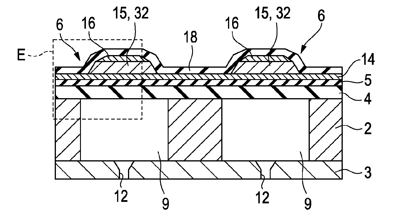
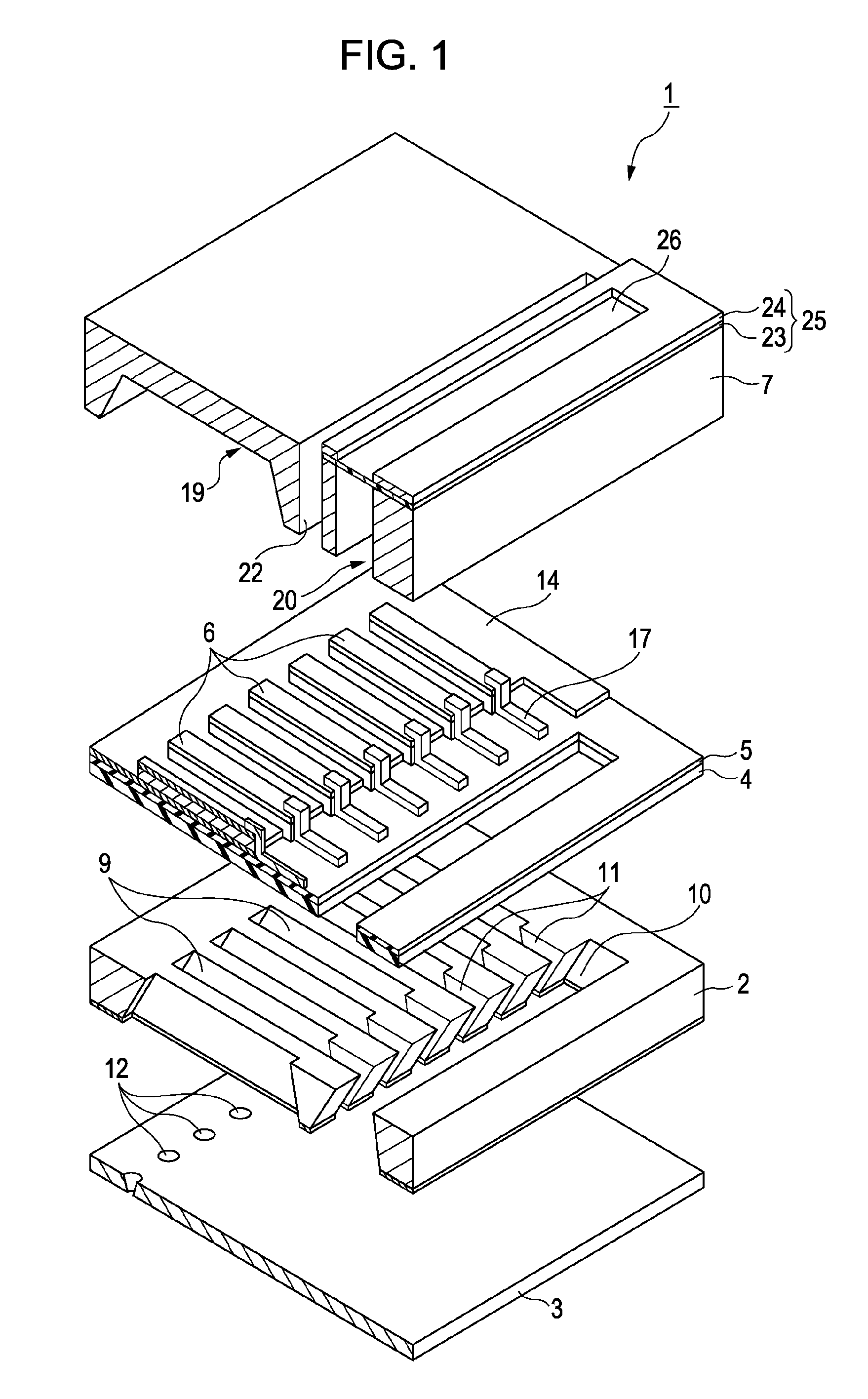
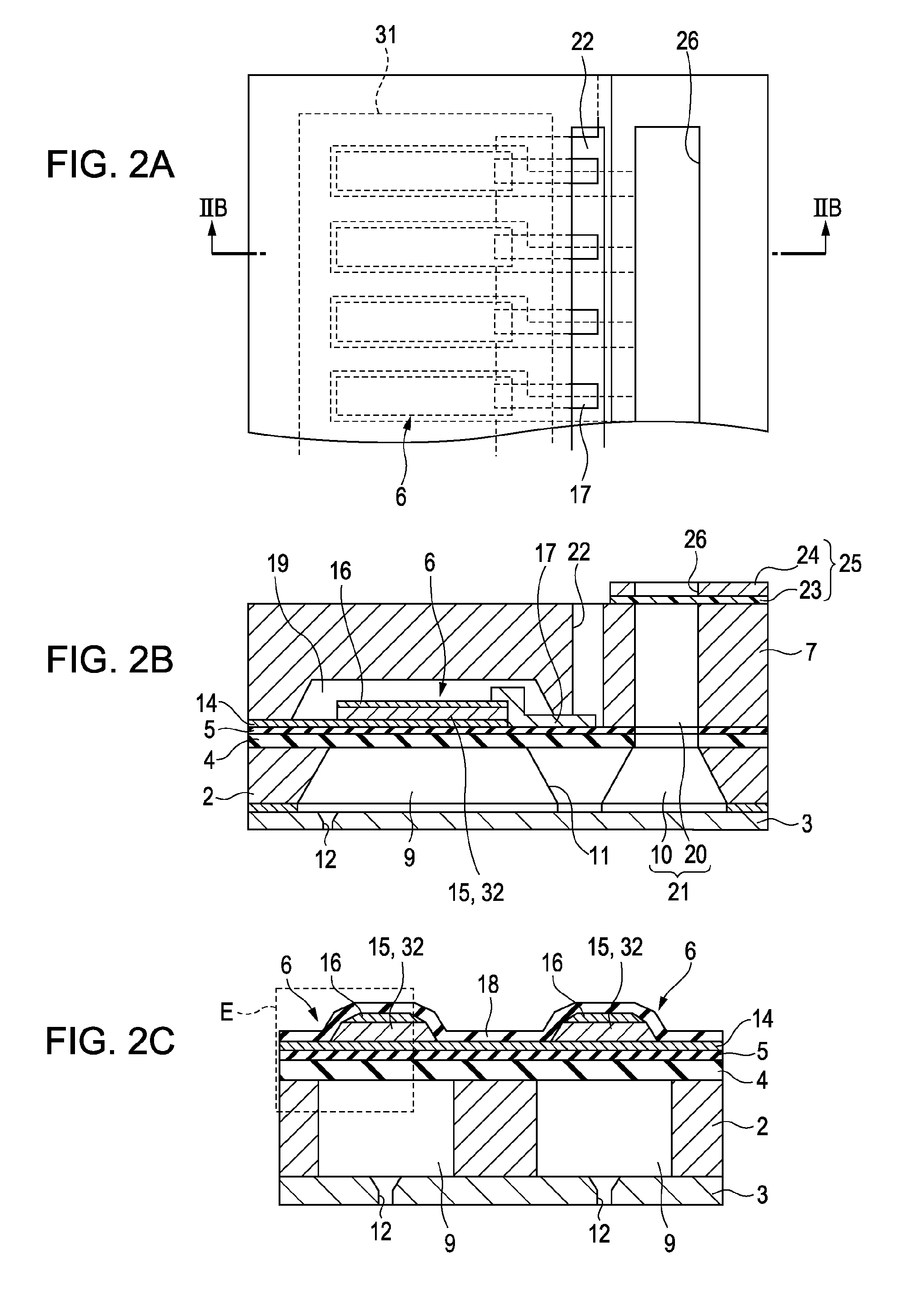
[0026]FIG. 1 is an exploded perspective view illustrating the configuration of a recording head 1 according to the embodiment. FIG. 2A is a plan view of the recording head 1, FIG. 2B is a cross-sectional view taken along the line IIB-IIB in FIG. 2A, and FIG. 2C is a cross-sectional view illustrating a major portion of a pressure-generating chamber 9 in a ...


PUM


Abstract

A piezoelectric element includes in a laminated state a piezoelectric layer, a first electrode formed on a first surface of the piezoelectric layer, and a second electrode formed on a second surface of the piezoelectric layer which is opposite to the first surface. The piezoelectric layer has a film thickness of 5 μm or less, and has a flat portion formed as a second surface in parallel with the first surface, and a lateral portion inclined downwardly from the flat portion towards the first surface. The second electrode has a central portion formed in parallel with the flat portion, and a slope portion inclined downwardly from the central portion towards the flat portion. The inclination angle of the slope portion to the flat portion is gentle as compared with the inclination angle of the lateral portion to the first surface.

Description

BACKGROUND[0001]1. Technical Field[0002]The present invention relates to a piezoelectric element which is employed as a drive source for a liquid ejecting head, such as an ink jet-type recording head, the liquid ejecting head, and a liquid ejecting apparatus, and more particularly, to a piezoelectric element capable of improved durability by suppressing stress concentration when the piezoelectric element is displaced, a liquid ejecting head, and a liquid ejecting apparatus.[0003]2. Related Art[0004]For example, a liquid ejecting apparatus is equipped with a liquid ejecting head capable of ejecting a liquid, the liquid ejecting apparatus ejecting various liquids from the liquid ejecting head. A typical example of the liquid ejecting apparatus is an image recording apparatus, such as an ink jet-type printer, equipped with an ink jet-type recording head (hereinafter referred to as a recording head) as the liquid ejecting head, in which liquid ink is ejected and impacted onto a recordin...

Claims


Application Information

Patent Timeline
Patent Type & Authority Applications(United States)
IPC IPC(8): B41J2/045H01L41/04B41J2/055B41J2/135B41J2/14B41J2/145H01L41/09H01L41/18H01L41/187H01L41/22H01L41/23H01L41/29H01L41/332
CPCB41J2/14233B41J2/161B41J2/1628B41J2/1631H01L41/0973B41J2002/14241B41J2002/14419B41J2002/14491B41J2202/11B41J2/1646H10N30/2047
Inventor SHIMADA, MASATO
Owner SEIKO EPSON CORP
Why Eureka
Try Eureka