Lens assembly and method of disposing optical member in ceramic lens frame

a technology of lens assembly and ceramic lens frame, which is applied in the field of lens assembly, can solve the problems of difficult to smoothly insert the lens, difficult to deliver appropriate optical performance to a camera mounted with such a lens assembly, and inner peripheral surface, and achieve excellent optical performan

Inactive Publication Date: 2010-04-01
FUJIFILM CORP
View PDF6 Cites 3 Cited by
  • Summary
  • Abstract
  • Description
  • Claims
  • Application Information

AI Technical Summary

Benefits of technology

[0012]In view of the above circumstances, the present invention provides a lens assembly that maintains excellent optical performance and a method of disposing an optical member in a ceramic lens frame of the lens assembly.
[0017]According to the lens assembly described above, the solid lubricant is applied to at least one of: the part of the inner peripheral surface, which part is to be in contact with at least the outer peripheral surface of the optical member; and the outer peripheral surface of the optical member. Subsequently, the optical member is inserted by being smoothly slid against the inner peripheral surface of the ceramic lens frame. Therefore, the rim of the optical member is prevented from chipping and the optical member is disposed at a correct position. For this reason, a camera into which the lens assembly described above is incorporated can sufficiently deliver predetermined optical performance.
[0018]In addition, since the solid lubricant is employed here, it is possible to prevent such a problem that when, for example, a liquid lubricant is used, optical performance of a lens assembly deteriorates due to the liquid lubricant flowing out.
[0019]In other words, according to the present invention, there is realized a lens assembly that maintains excellent optical performance.
[0023]There are various types of ceramic including the porous ceramic described above. The porous ceramic has a low reflectivity in a visible-light area and thus is suitably applied to a lens frame of a camera. However, since the porous ceramic has a high porosity, the surface of the porous ceramic is more uneven than ordinary types of ceramic. When the solid lubricant as described above is used, even though the ceramic is porous, entering its pores can be prevented and thus a sufficient effect can be achieved.

Problems solved by technology

When the material of the lens assembly 1 illustrated in FIG. 1 is ceramic, the lens assembly 1 has such a drawback that it is more difficult to smoothly insert the lenses L1 trough L4 and the spacing rings SP1 through SP3 as compared to when the material is a metal or the like, because the inner peripheral surface of the lens frame 10 made of ceramic is uneven.
When the lens assembly has the optical members whose rim is chipped or which are not placed at correct positions, it is impossible for a camera mounted with such a lens assembly to deliver appropriate optical performance.

Method used


Image

  • Lens assembly and method of disposing optical member in ceramic lens frame
  • Lens assembly and method of disposing optical member in ceramic lens frame
  • Lens assembly and method of disposing optical member in ceramic lens frame

Examples


Embodiment Construction

[0031]An embodiment of the present invention will be described.

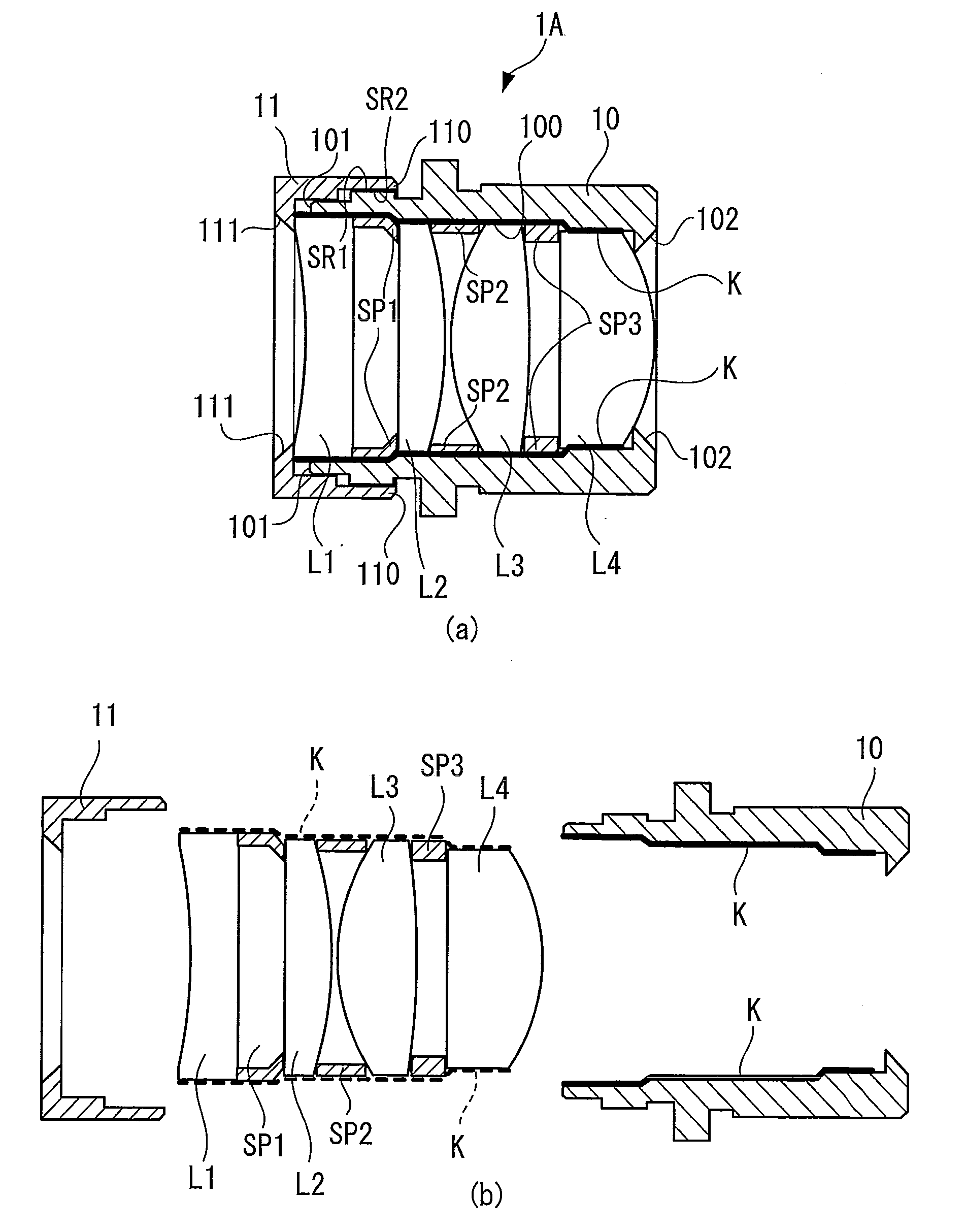
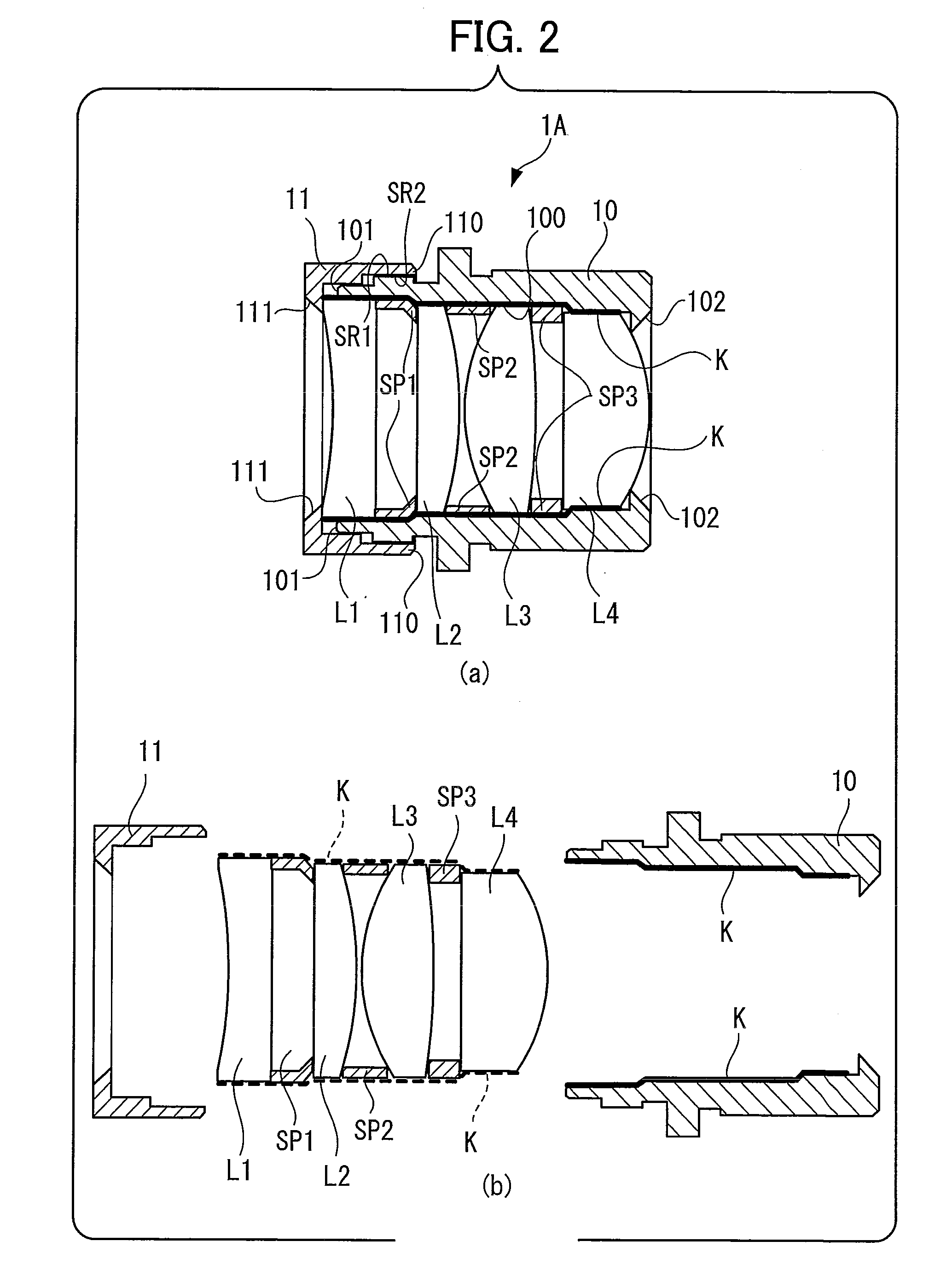
[0032]FIG. 2 is a diagram that depicts the structure of a lens assembly 1A of the present embodiment.

[0033]Part (a) of FIG. 2 is the same as FIG. 1 except that a solid lubricant K is applied. Part (b) of FIG. 2 illustrates a pressing ring 11, a lens frame 10 and a lens group (lenses L1 through L4) in an exploded state.

[0034]As illustrated in part (b) of FIG. 2, after the lubricant K is applied to a part of the inner peripheral surface of the lens frame 10, which part is to be in contact with at least the outer peripheral surfaces of optical members, the lenses L1 through L4 and spacing rings SP1 through SP3 serving as the optical members are inserted into the lens frame 10. In this structure, the lenses L1 through L4 and spacing rings SP1 through SP3 are smoothly inserted into the lens frame 10, which prevents the rim of any of the lenses L1 through L4 from being chipped and also allows the optical members including the ...


PUM

PropertyMeasurementUnit
porosityaaaaaaaaaa
temperaturesaaaaaaaaaa
temperatureaaaaaaaaaa

Abstract

A lens assembly has: optical members including lenses and spacing rings; and a ceramic lens frame into which the optical members are inserted. A solid lubricant is applied to at least one of a part of the inner peripheral surface of the ceramic lens frame, which part is to be in contact with at least the outer peripheral surfaces of the optical members, and the outer peripheral surfaces of the optical members. Subsequently, the lenses and spacing rings are alternately inserted into the ceramic lens frame and then pressed by a pressing ring.

Description

BACKGROUND OF THE INVENTION[0001]1. Field of the Invention[0002]The present invention relates to a lens assembly equipped with an optical member and a ceramic lens frame having a hollow part into which the optical member is inserted, and to a method of disposing the optical member in the ceramic lens frame of the lens assembly.[0003]2. Description of the Related Art[0004]In recent years, automobiles have been provided with cameras. Meanwhile, nowadays, automobiles are equipped with display screens thanks to the widespread use of car navigation systems. Therefore, many of cameras installed in automobiles can display the state of a blind spot for a driver on a display screen provided in front of the driver's seat. Incidentally, automobiles may be left outdoors in hot summer and in freezing winter and therefore, a camera installed in an automobile is required to operate properly over an extremely wide range of temperatures. In order to guarantee the proper operation of a vehicle-mounte...

Claims


Application Information

Patent Timeline
Patent Type & Authority Applications(United States)
IPC IPC(8): G02B7/02
CPCG02B7/021
Inventor TANAKA, YASUNORISAKAI, YUYATAKI, IKUO
Owner FUJIFILM CORP
Why Eureka
Try Eureka