Sound image localization processor, Method, and program

a sound image and localization processor technology, applied in the direction of stereophonic arrangments, transducer details, earpiece/earphone attachments, etc., to achieve the effect of small structure and highly precise distance sens

Active Publication Date: 2010-04-01
OKI ELECTRIC IND CO LTD
View PDF2 Cites 62 Cited by
  • Summary
  • Abstract
  • Description
  • Claims
  • Application Information

AI Technical Summary

Benefits of technology

[0021]The present invention can provide a sound localization processor th

Problems solved by technology

In principle the virtual sound source may be disposed at any location, provided HRTFs can be obtained for all poi

Method used


Image

  • Sound image localization processor, Method, and program
  • Sound image localization processor, Method, and program
  • Sound image localization processor, Method, and program

Examples


first embodiment

(A) First Embodiment

[0032]A first embodiment of the sound image localization processor, method, and program of the present invention will be described with reference to the drawings below.

[0033](A-1) Structure of the First Embodiment

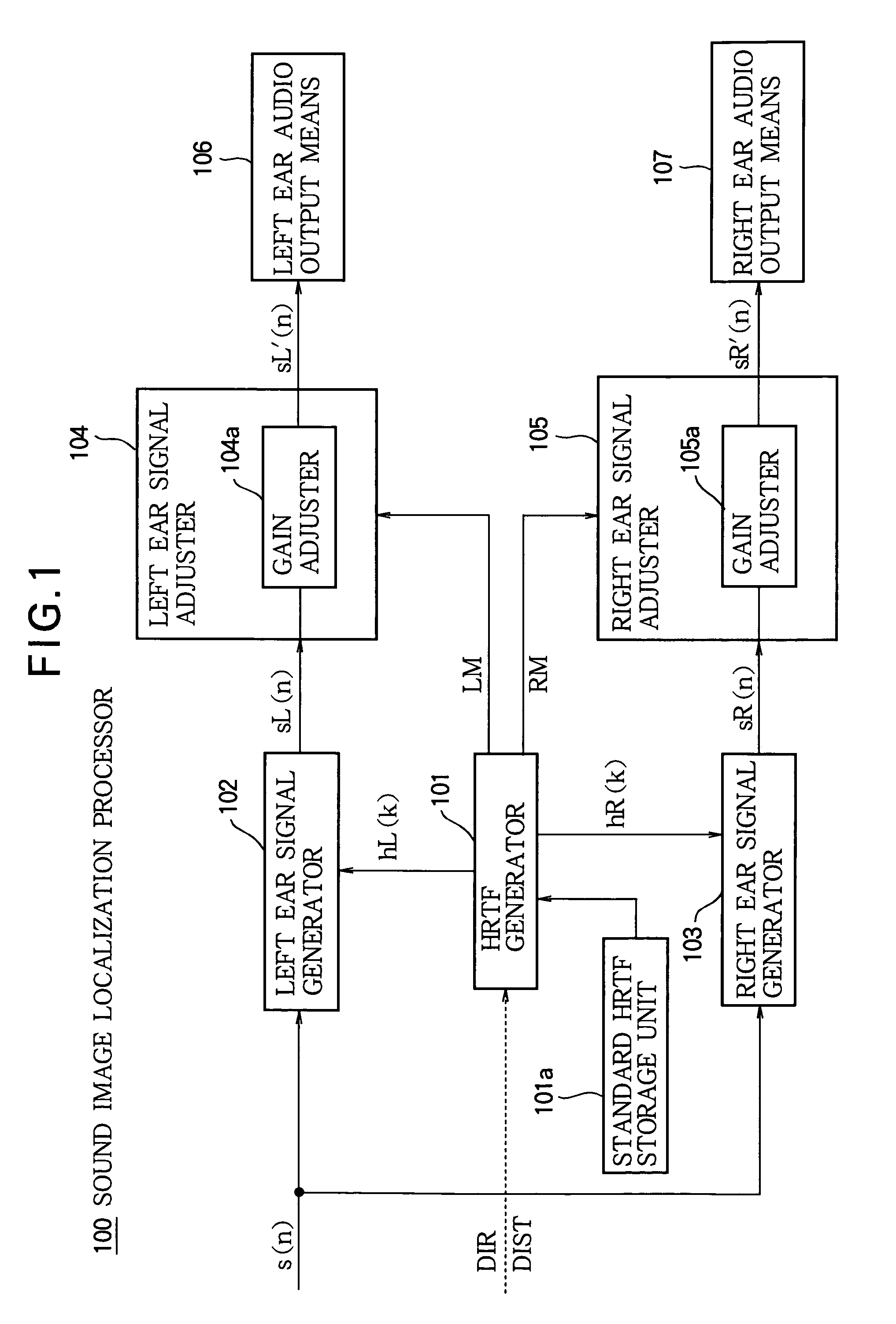
[0034]FIG. 1 is a block diagram showing the overall structure of the sound image localization processor in the first embodiment.

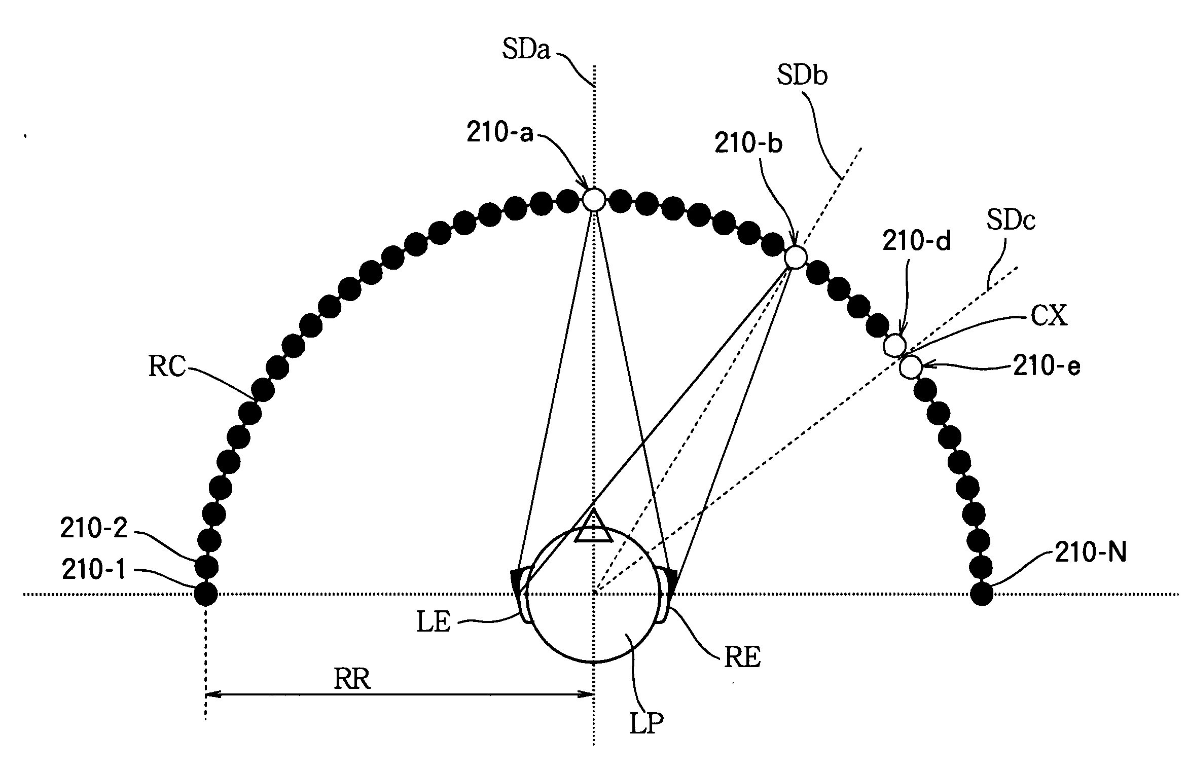
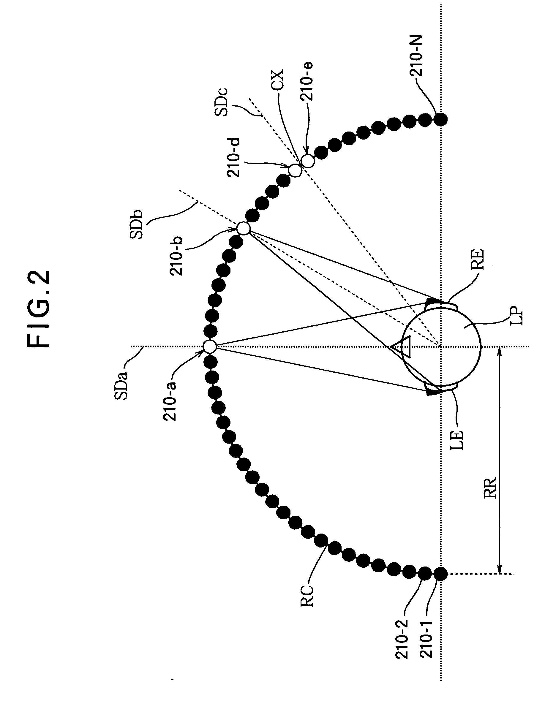
[0035]When given a sound-source signal or a source audio listing signal s(n) on which a sense of direction and distance is to be imprinted, with information DIR about the desired direction (‘DIR’ is used below to indicate both the direction information and the direction itself) and information DIST about the desired distance (‘DIST’ is used below to indicate both the distance information and the distance itself), a sound image localization processor 100 imprints a sense of direction and a sense of distance on the signal denoted s(n) such that it sounds to the listener as if sound produced by the signal s(n) comes from a virtual ...

second embodiment

(B) Second Embodiment

[0084]A second embodiment of the sound image localization processor, method, and program of the present invention will be described below with reference to the drawings.

[0085](B-1) Structure of the Second Embodiment

[0086]FIG. 5 is a block diagram showing the overall structure of the sound image localization processor in the second embodiment; parts identical to or corresponding to parts in the above-described FIG. 1 are indicated by identical or corresponding reference characters.

[0087]The sound image localization processor 100A in the second embodiment has a structure in which a frequency component adjuster 104b and a frequency component adjuster 105b are added to the left ear signal adjuster 104 and right ear signal adjuster 105 of the sound image localization processor 100 in the first embodiment. The differences between the sound image localization processor 100A and the sound image localization processor 100 in the first embodiment will be described below.

[...


PUM


Abstract

There are provided: a means (101a) for storing standard head related transfer functions for reference positions from a virtual listener; a means (101) for, when given information (DIR, DIST) about a virtual sound source position, forming head related transfer functions (hL(k), hR(k)) as left ear and right ear head related transfer functions by selecting one of the stored standard head related transfer functions or by selecting two or more of them and interpolating; means (102, 103) for imprinting a sense of direction and distance on the audio listening signal by using the head related transfer functions thus obtained; and means (104, 105) for correcting a distance related to the obtained head related transfer functions and the sense of distance to the virtual sound source position, in the audio listening signals (sL(n), sR(n)) given the sense of direction and distance or the source audio listening signal (s(n)). A highly precise sense of distance can be provided in a small structure.

Description

FIELD OF THE INVENTION[0001]The present invention relates to a sound image localization processor, method, and program that can be used for sound image localization in, for example, a sound output device.BACKGROUND ART[0002]A person recognizes the direction of and distance to a sound source from the difference between the sound heard by the left and right ears. The difference between the sound heard by the left and right ears arises from the different distances from the sound source to the left and right ears, that is, the different characteristics (frequency characteristics, phase characteristics, loudness, etc.) imprinted on the sound as it propagates through space. By intentionally imparting a difference in these characteristics to a sound-source signal, it is possible to have the signal recognized as coming from an arbitrary direction and distance. A head related transfer function (HRTF) is a well-known way to represent the characteristics acquired by a sound source during propa...

Claims


Application Information

Patent Timeline
IPC IPC(8): H04R5/00
CPCH04S1/005H04S2420/01H04S7/302
Inventor AOYAGI, HIROMI
Owner OKI ELECTRIC IND CO LTD
Why Eureka
Try Eureka