Image forming apparatus

a technology of forming apparatus and resin frame, which is applied in the direction of electrographic process apparatus, instruments, optics, etc., can solve the problems of affecting the holding force of the resin frame on the metal frame, the resin frame tends to be distorted at the area including the first length,

Active Publication Date: 2010-04-01
BROTHER KOGYO KK
View PDF4 Cites 23 Cited by
  • Summary
  • Abstract
  • Description
  • Claims
  • Application Information

AI Technical Summary

Benefits of technology

[0010]Thus, according to the above configuration, the resin frames can be attached to the metal frames with substantial holding force whilst prevented from experiencing a large amount of thermal distortion so that the resin frames are prevented from being exhausted earlier.

Problems solved by technology

Further, the resin frame is fixed to the metal frame at the fixing structure; therefore, when the resin frame tends to expand or contract with respect to the metal frame, the resin frame tends to be distorted at an area including the first length.
On the other hand, when the first length is smaller than the second length, substantial holding force to hold the resin frame on the metal frame may not be achieved; however, according to the above configuration, the pressing pieces are provided in positions outside closer to outer edges of the resin frame with respect to the first positioning structure and the fixing structure of the resin frame.

Method used


Image

  • Image forming apparatus
  • Image forming apparatus
  • Image forming apparatus

Examples


Embodiment Construction

[0031]Hereinafter, an embodiment according to an aspect of the present invention will be described with reference to the accompanying drawings.

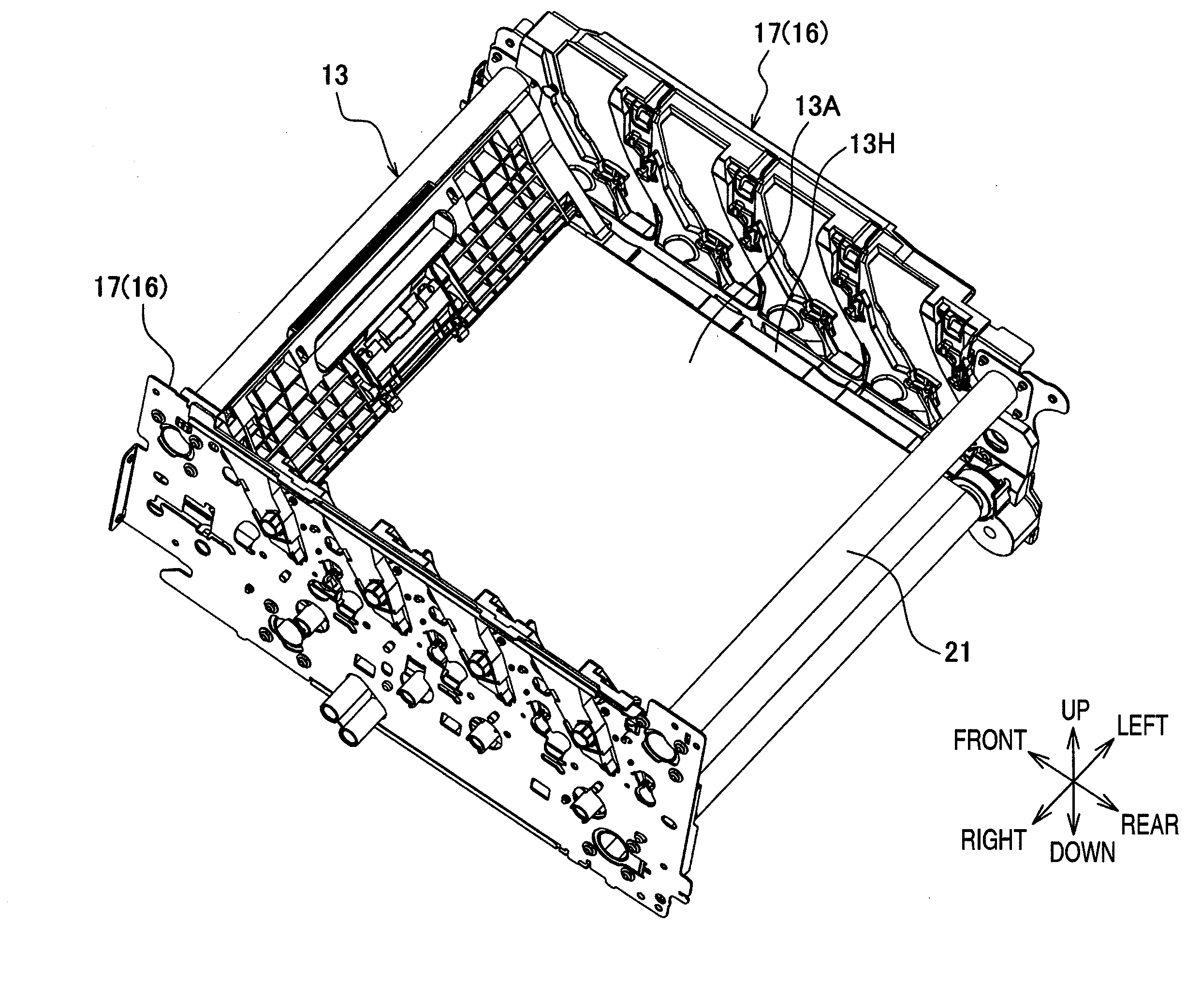
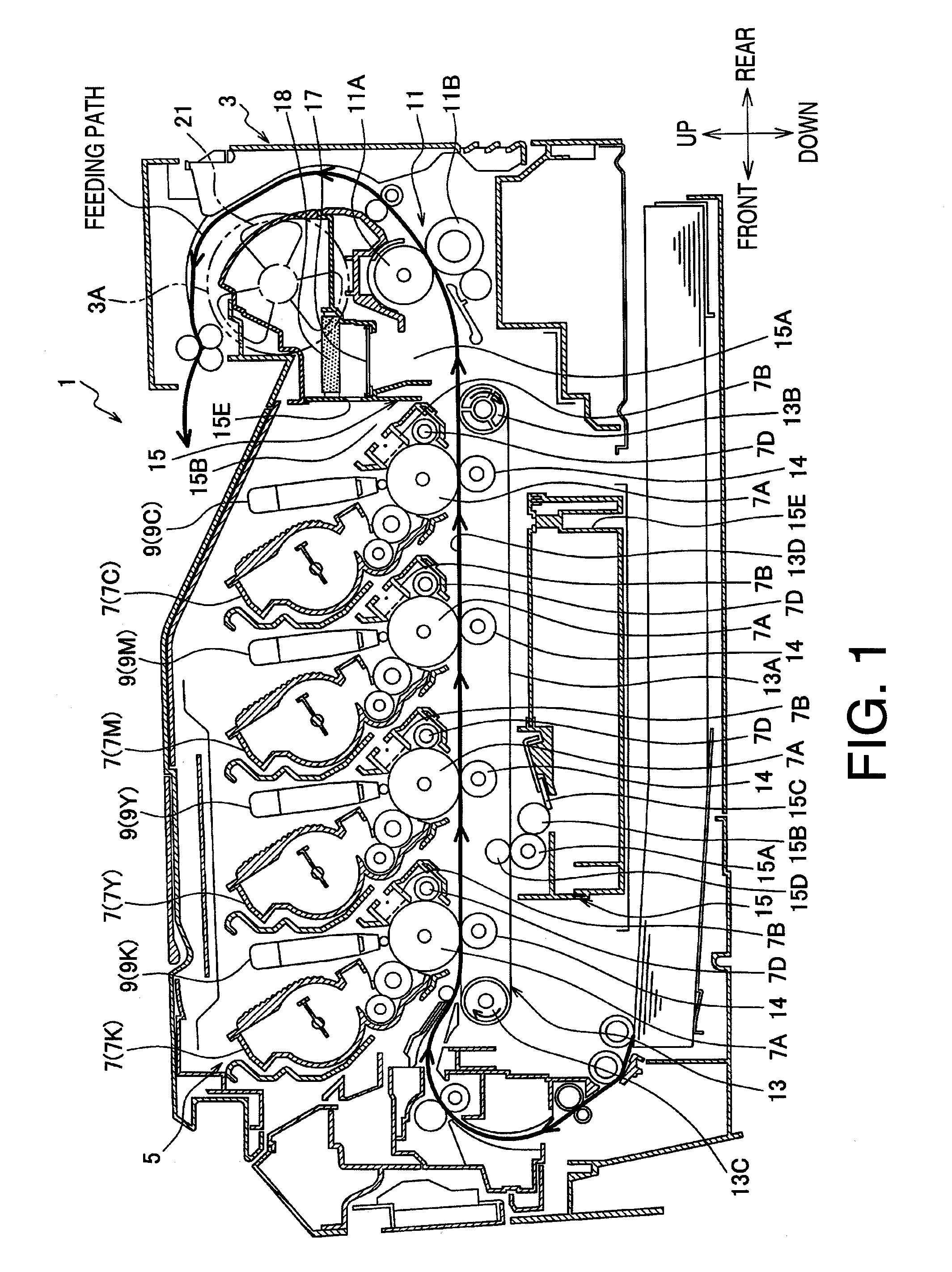
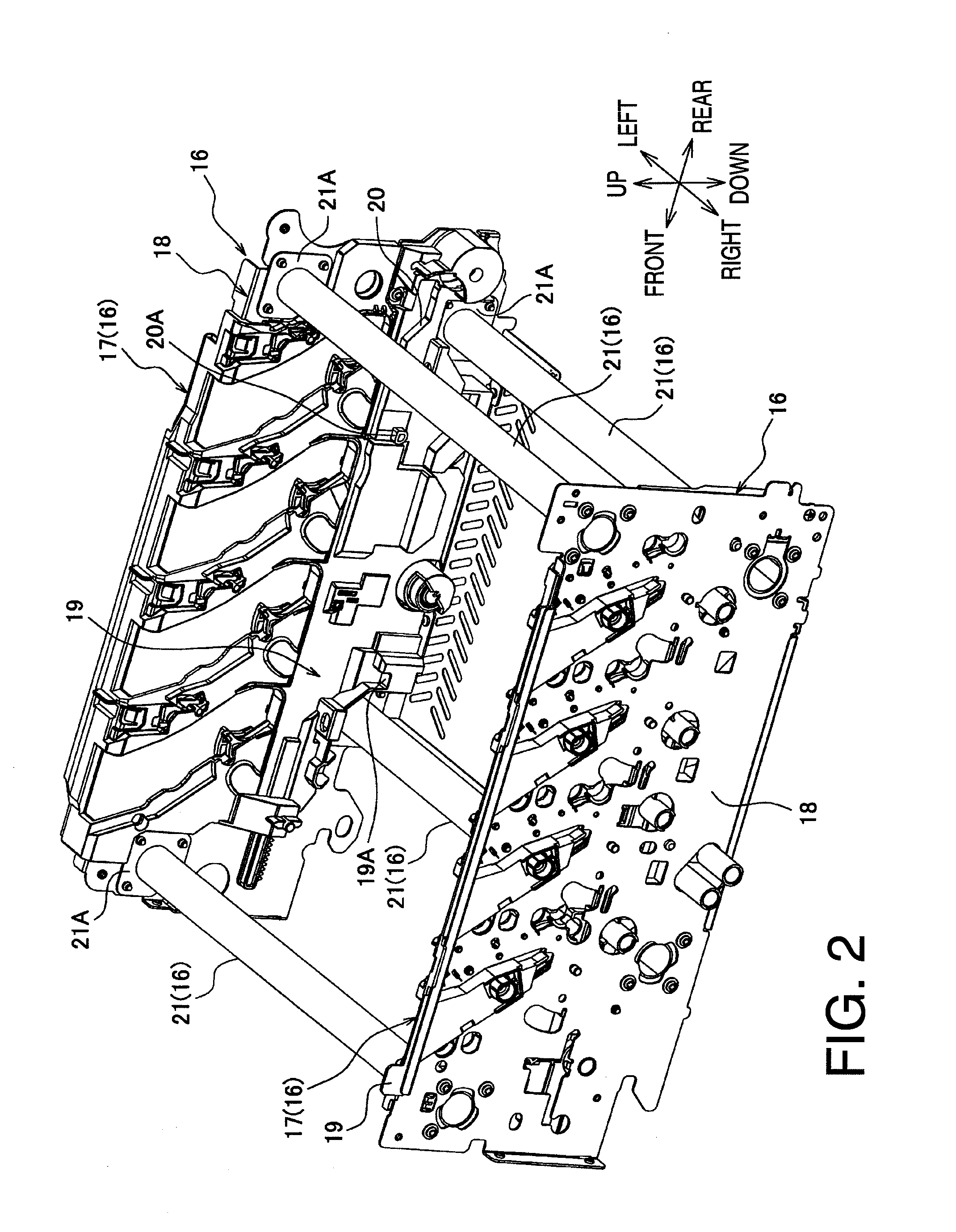
[0032]FIG. 1 is a cross-sectional side view of a printer 1 as an example of an image forming apparatus according to an embodiment of the present invention. In the present embodiment, directions concerning the printer 1 will be referred to based on the orientation of the printer 1 shown in FIG. 1. A right-left direction of the printer 1 refers to a direction perpendicular to the cross-section of the printer 1 in FIG. 1, and is also referred to as a widthwise direction. The printer 1 includes a chassis 3, in which an image forming unit 5 is stored. An up-down direction in FIG. 1 may also be referred to as a vertical direction. A recording sheet (e.g., paper and an OHP sheet) is fed in the image forming unit 5 and processed to have an image formed in a developer agent transferred on a surface thereof. The image forming unit 5 includes processing...


PUM


Abstract

An image forming apparatus is provided. The image forming apparatus includes a plurality of detachable unit components and a frame assembly to hold the detachable unit components in predetermined positions in the image forming apparatus. The frame assembly includes a pair of metal frames and a pair of resin frames, each of which is attached to one of the metal frames. Each of the metal frames includes a first positioning structure, which corresponds to an original point of the metal frame, a first fixing structure, a second positioning structure, wherein each of the resin frames includes, a first positioning structure, which corresponds to an original point of the resin frame, a fixing structure, a second positioning structure, and a plurality of pressing pieces, by which the resin frame is pressed against one of the metal frame.

Description

CROSS REFERENCE TO RELATED APPLICATION[0001]This application claims priority from Japanese Patent Application No. 2008-248597, filed on Sep. 26, 2008,the entire subject matter of which is incorporated herein by reference.BACKGROUND[0002]1. Technical Field[0003]An aspect of the present invention relates to an image forming apparatus having a removable unit component such as a belt unit.[0004]2. Related Art[0005]When detachable unit components of an image forming apparatus such as a belt unit are installed in the image forming apparatus, the unit components are often held by a frame structure of the image forming apparatus, which is, for example, disclosed in United States Patent Application Publication No. 2008 / 0003015 A1. According to the disclosure, the frame structure includes a pair of metal frames with enhanced intensity and a pair of resin frames attached to the metal frames. The unit components are placed in the frame structure, specifically in positions defined by positioning...

Claims


Application Information

Patent Timeline
Patent Type & Authority Applications(United States)
IPC IPC(8): G03G21/16
CPCG03G15/1685G03G2215/1623G03G21/1642G03G2221/1678G03G21/1619G03G2221/1642
Inventor NAKASHIMA, ATSUHISA
Owner BROTHER KOGYO KK
Why Eureka
Try Eureka