System and method to stablize a spinal column including a spinolaminar locking plate

a locking plate and spinal column technology, applied in the field of systems and methods to stabilize the spinal column, can solve problems such as compression of spinal nerve roots and spinal nerves

Active Publication Date: 2010-04-01
KONDRASHOV DIMITRIY G
View PDF89 Cites 157 Cited by
  • Summary
  • Abstract
  • Description
  • Claims
  • Application Information

AI Technical Summary

Problems solved by technology

As individuals age, degenerative changes accumulate, affecting the vertebral discs, vertebra, facet joints, and ligaments in the thoracic and lumbar region and can lead to compression of spinal nerves and spinal nerve roots.

Method used


Image

  • System and method to stablize a spinal column including a spinolaminar locking plate
  • System and method to stablize a spinal column including a spinolaminar locking plate
  • System and method to stablize a spinal column including a spinolaminar locking plate

Examples


Embodiment Construction

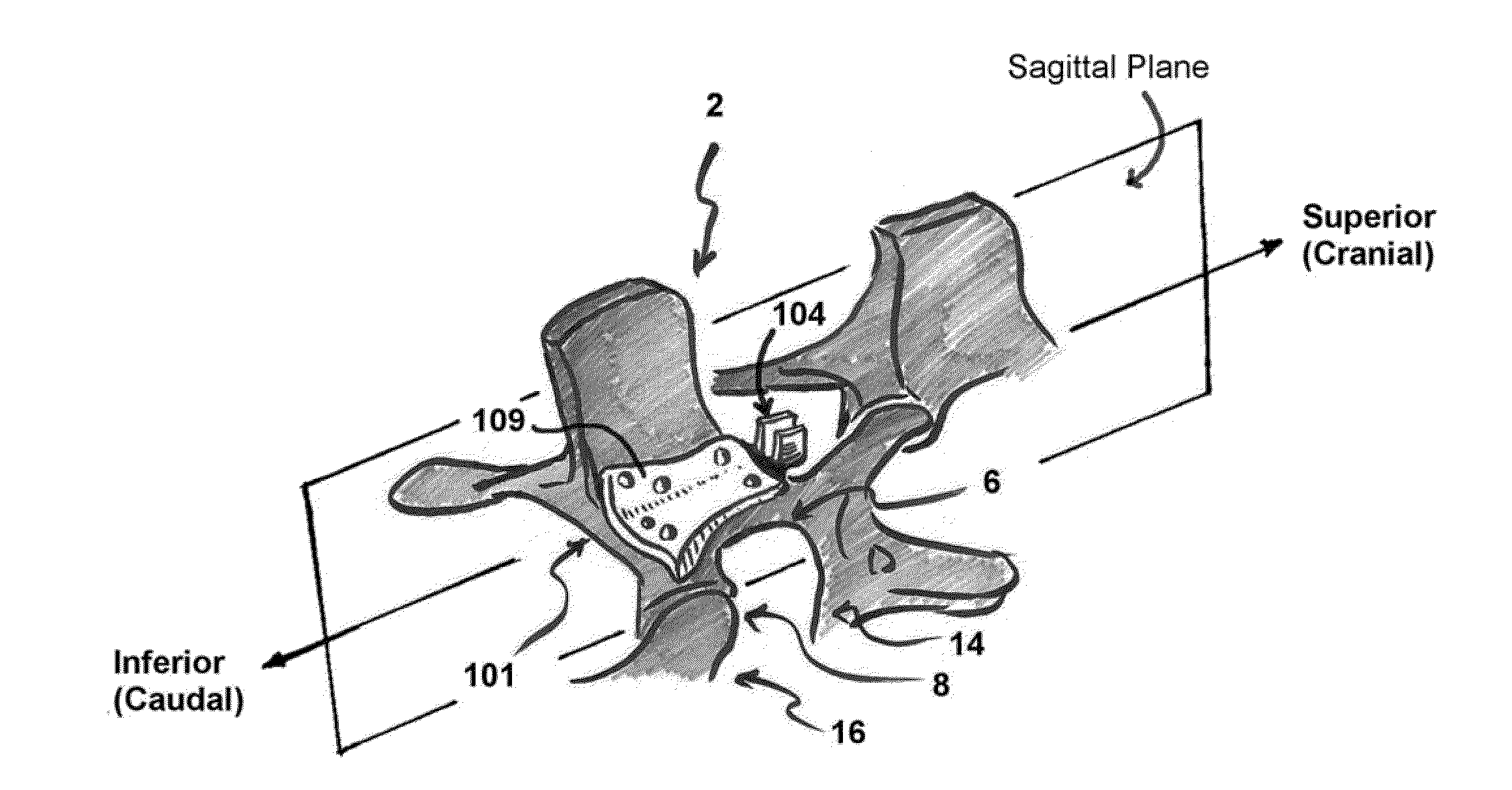
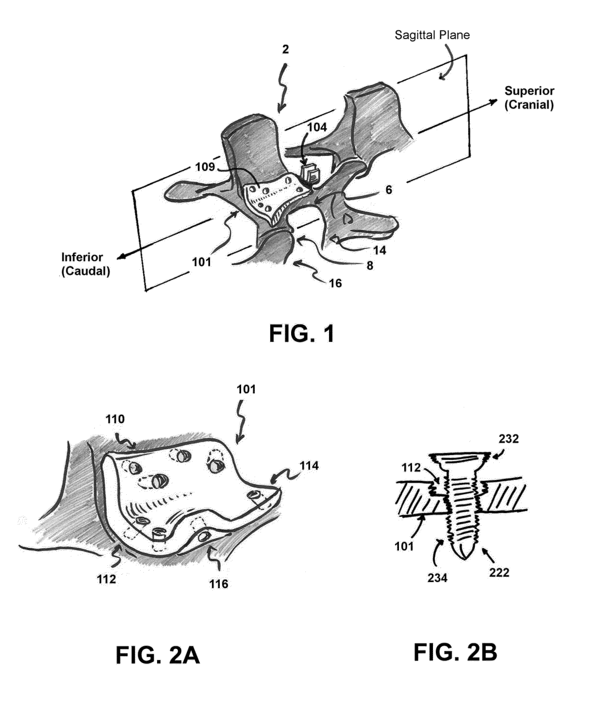
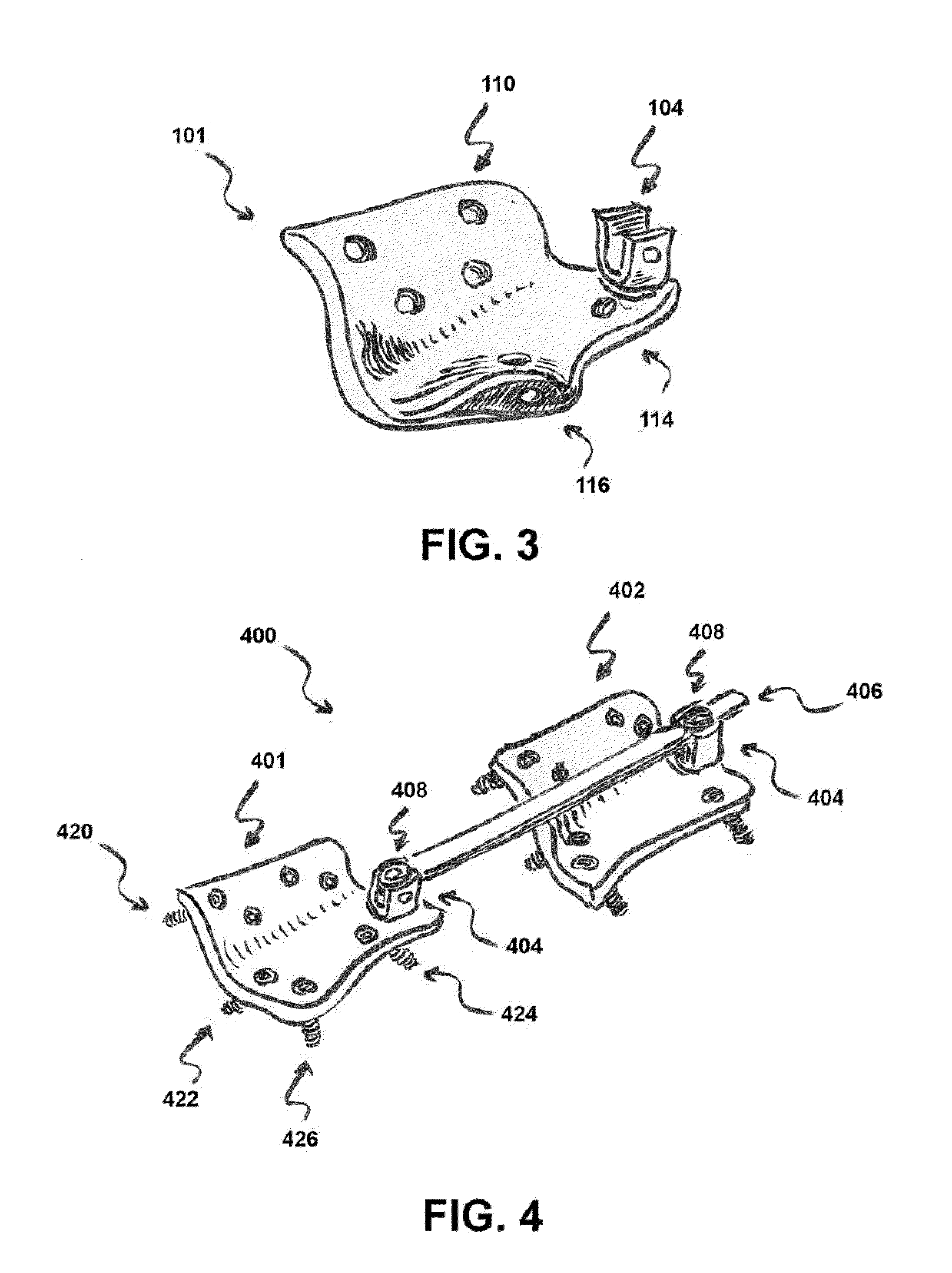
[0019]The following description is of the best modes presently contemplated for practicing various embodiments of the present invention. The description is not to be taken in a limiting sense but is made merely for the purpose of describing the general principles of the invention. The scope of the invention should be ascertained with reference to the claims. In the description of the invention that follows, like numerals or reference designators will be used to refer to like parts or elements throughout. In addition, the first digit of a reference number identifies the drawing in which the reference number first appears. Reference numerals used in a drawing may or may not be referenced in the detailed description specific to such drawing if the associated element is described elsewhere. Further, the terms “vertical” and “horizontal” are used throughout the detailed description to describe general orientation of structures relative to the spine of a human patient that is standing.

[00...


PUM


Abstract

A system adapted to be implanted in a patient to stabilize a spinal column of the patient comprises an anchoring plate having a shape generally conformal with at least a portion of a lamina associated with a targeted vertebra of the spinal column. The anchoring plate is securable to the targeted vertebra by two or more screws. A mounting bracket adapted to receive an secure a rod is connected with the anchoring plate.

Description

CLAIM TO PRIORITY[0001]This application claims priority to U.S. Provisional Application No. 61 / 194,516, filed Sep. 29, 2008, entitled “SPINOLAMINAR LOCKING PLATE UTILIZING ANATOMIC PRE-CONTOURED DESIGN AND LOCKING”, incorporated herein by reference.TECHNICAL FIELD[0002]Embodiments of the present invention relate to systems and methods to stabilize a spinal column.BACKGROUND OF INVENTION[0003]Degenerative changes of the spinal column are the most common underlying cause of chronic back pain. The peak incidence of symptoms occurs between the ages of 30 and 50, a period of life during which the most strenuous job and sports-related activities occur. As individuals age, degenerative changes accumulate, affecting the vertebral discs, vertebra, facet joints, and ligaments in the thoracic and lumbar region and can lead to compression of spinal nerves and spinal nerve roots.[0004]It can be desirable to reduce the compression of spinal nerves and spinal nerves by stabilizing the spinal colum...

Claims


Application Information

Patent Timeline
Patent Type & Authority Applications(United States)
IPC IPC(8): A61B17/70A61B17/86
CPCA61B17/7044A61B17/7064A61B17/7059A61B17/7055
Inventor KONDRASHOV, DIMITRIY G.
Owner KONDRASHOV DIMITRIY G
Why Eureka
Try Eureka