Method for the monitoring, control and optimization of filling equipment for foods and beverages, such as, for beverage bottles

a technology for filling equipment and food and beverages, applied in the field of monitoring, control and optimization of filling plants and equipment, can solve the problems of increasing the number of personnel required, the risk of a malfunction or disruption of operation in other parts of the plant, and the complex and varied opto-electronic system according to the present application

Active Publication Date: 2010-04-01
KHS GMBH
View PDF16 Cites 16 Cited by
  • Summary
  • Abstract
  • Description
  • Claims
  • Application Information

AI Technical Summary

Benefits of technology

[0010]An object of the present application is essentially to monitor a plant or machine. In the context of this plant or machine monitoring, for example, it becomes unnecessary or undesired to assign personnel who work inside the plant to monitor malfunctions and disruptions and / or to control the output of the plant, or at least to significantly reduce the number of personnel required or desired for these activities. Moreover, additional functions can also be realized to increase the safety of personnel and the reliability of the process.SUMMARY
[0016]In an additional embodiment of the present application, the use of recognition systems of this type makes it possible to essentially guarantee or promote fully automated operation even in the event of a disruption or malfunction, i.e. an error detection can immediately or substantially immediately and automatically result in the execution of a control routine which can also include an automatic error resolution.
[0023]Depending on the determined level of occupation of the corresponding buffer line, the throughput of an individual machine can be in one possible embodiment regulated, which makes it possible to eliminate, restrict, and / or minimize complex and expensive wiring, among other things.
[0025]As a result of the use of a thermal imaging camera according to the present application, in combination with a downstream image processing and the use of the results (measured temperatures) to control the plant, the reliability and safety of the process can be further increased, without any increased effort or expense for wiring, for example.
[0028]The systems according to the present application can also be used to realize a protection function for the persons or employees who work inside the plant. It thereby becomes possible, for example, to analyze the current location and / or the current bodily position and / or the movements made in comparison to images taken previously of any person inside the plant.

Problems solved by technology

In the context of this plant or machine monitoring, for example, it becomes unnecessary or undesired to assign personnel who work inside the plant to monitor malfunctions and disruptions and / or to control the output of the plant, or at least to significantly reduce the number of personnel required or desired for these activities.
On the other hand, the opto-electronic system according to the present application is much more varied and complex.
With the use of the present application, for example, the number of objects moved, e.g. the number of bottles to be filled or already filled, can also be called up, as can the three-dimensional position of bottles, such as a condition in which a bottle has fallen over and thus represents the risk of a malfunction or disruption of operation in other parts of the plant.
More precise information on the level of occupation is currently not determined, because a larger number of jam switches means a significant increase in the costs of design and fabrication.

Method used


Image

  • Method for the monitoring, control and optimization of filling equipment for foods and beverages, such as, for beverage bottles
  • Method for the monitoring, control and optimization of filling equipment for foods and beverages, such as, for beverage bottles
  • Method for the monitoring, control and optimization of filling equipment for foods and beverages, such as, for beverage bottles

Examples


Embodiment Construction

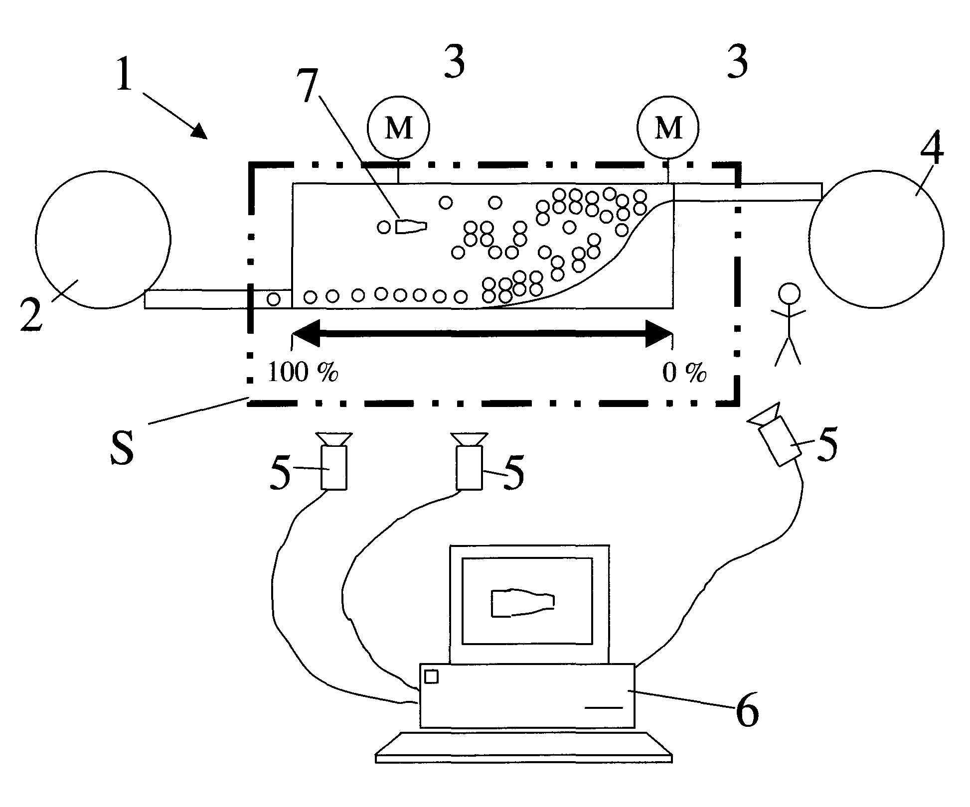
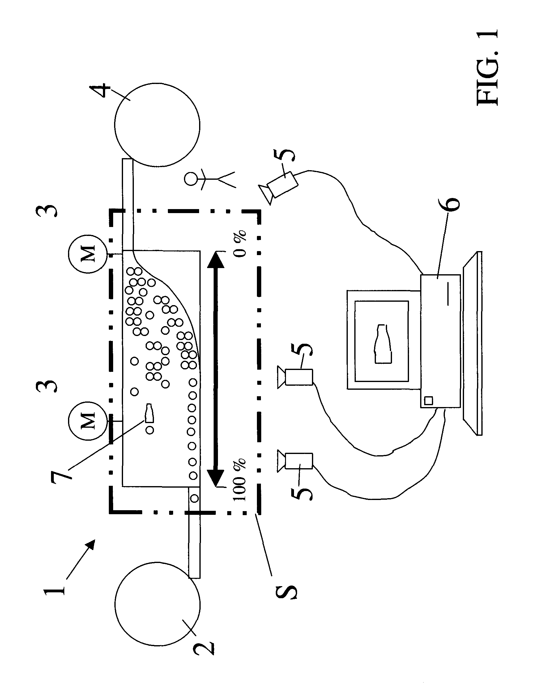
[0041]A plant which is illustrated symbolically and is designated 1 in general, is designed to be used for the filling of beverage bottles, for example. The bottles are thereby fed from a first machine 2 via transport segments designated 3 to an additional machine 4. The transport segments 3 are driven by drive motors M.

[0042]For the monitoring of the plant, and also for example for the monitoring of the level of occupation of the transport segments and for the control of the plant, cameras which are designated 5 in general are provided, the data from which are fed to a data processing system 6, so that the plant can be controlled, and in one possible embodiment so that malfunctions and disruptions can be detected and resolved automatically. The scaling or the level of occupation of the transport line is indicated symbolically by a double arrow.

[0043]In the illustrated possible embodiment, the current position of a person inside the plant is also monitored. This person, for example,...


PUM


Abstract

A method for the monitoring, control and optimization of filling equipment for foods and beverages, such as, for beverage bottles. The abstract of the disclosure is submitted herewith as required by 37 C.F.R. §1.72(b). As stated in 37 C.F.R. §1.72(b): A brief abstract of the technical disclosure in the specification must commence on a separate sheet, preferably following the claims, under the heading “Abstract of the Disclosure.” The purpose of the abstract is to enable the Patent and Trademark Office and the public generally to determine quickly from a cursory inspection the nature and gist of the technical disclosure. The abstract shall not be used for interpreting the scope of the claims. Therefore, any statements made relating to the abstract are not intended to limit the claims in any manner and should not be interpreted as limiting the claims in any manner.

Description

CONTINUING APPLICATION DATA[0001]This application is a Continuation-In-Part application of International Patent Application No. PCT / EP2008 / 001775, filed on Mar. 6, 2008, which claims priority from Federal Republic of Germany Patent Application No. 10 2007 014 802.1, filed on Mar. 28, 2007. International Patent Application No. PCT / EP2008 / 001775 was pending as of the filing date of this application. The United States was an elected state in International Patent Application No. PCT / EP2008 / 001775.BACKGROUND[0002]1. Technical Field[0003]The present application relates to a method for the monitoring, control and optimization of filling plants and equipment for products of types in which solid or liquid products are filled into containers such as cans, bottles or similar containers. The present application relates in one possible embodiment to filling plants and equipment for beverages.[0004]2. Background Information[0005]Background information is for informational purposes only and does n...

Claims


Application Information

Patent Timeline
Patent Type & Authority Applications(United States)
IPC IPC(8): G06F7/00G05D9/12G05D7/06H04N7/18
CPCB67C3/007B67B3/26
Inventor TILL, VOLKERMUSZINSKI, OLAFFUSSMANN, ROLFSTIENEN, THOMASSCHOLZ, ULRICHMENKE, HERBERT
Owner KHS GMBH
Why Eureka
Try Eureka