
Computer system and method for sharing PCI devices thereof

a technology of pci devices and computer systems, applied in computing, instruments, electric digital data processing, etc., can solve the problems of reducing the it budget of a company, increasing the number of servers, and wasting spa

Inactive Publication Date: 2010-04-01
HITACHI LTD
View PDF17 Cites 79 Cited by
  • Summary
  • Abstract
  • Description
  • Claims
  • Application Information

AI Technical Summary

Benefits of technology

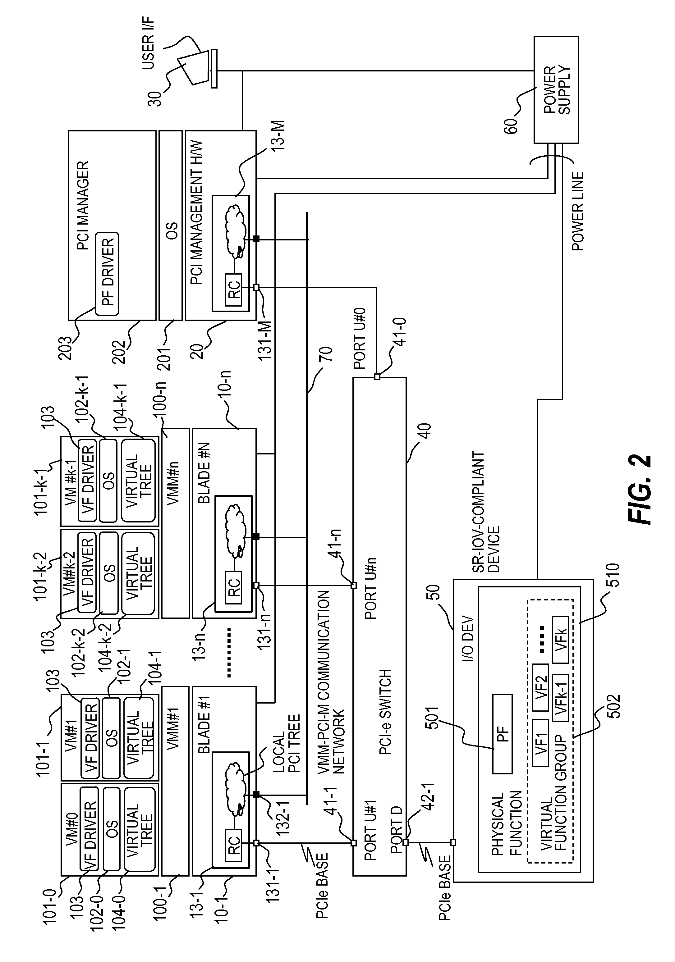
[0010]In Single Root IO Virtualization (hereinafter abbreviated as SR-IOV) mentioned above as a prior art example, a physical function (PF) of a single I / O device can provide a plurality of virtual functions (VFs). The plurality of virtual functions are used exclusively by a plurality of OS instances within the same blade, thereby allowing the OS instances to share a single I / O device that is compliant with SR-IOV.
[0012]An SR-IOV-compliant I / O device, which only needs to have a single physical function, can be procured at a lower cost than that of obtaining an MR-IOV-compliant I / O device.
[0014]On the other hand, if an I / O device that is compliant with MR-IOV described above is used in the blade server of the above-mentioned prior example when a plurality of blades are to share an I / O device, sharing a single I / O device among a plurality of blades is possible, but an MR-IOV-compliant I / O device costs higher to procure than an SR-IOV-compliant I / O device and pushes up introduction cost.
[0016]This invention has been made in view of the above-mentioned problems, and it is therefore an object of this invention to provide an inexpensive way to share an I / O device loaded in an I / O drawer among a plurality of blades in a blade server which has the plurality of blades.

Problems solved by technology

However, an increase in server count increases running cost and cuts into the IT budget of a company to a degree that it poses a problem.
A resultant problem is that an I / O slot is reserved even for a blade that uses other I / O cards than NICs infrequently or not at all, which is a waste of space.
Another problem is that a blade whose use requires many I / O cards (for example, a hot-standby architecture set up among a plurality of blades) cannot be allocated with more I / O slots than the count of I / O slots within an I / O drawer.

Method used


Image

  • Computer system and method for sharing PCI devices thereof
  • Computer system and method for sharing PCI devices thereof
  • Computer system and method for sharing PCI devices thereof

Examples


Embodiment Construction

[0044]An embodiment of this invention is described below with reference to the accompanying drawings.

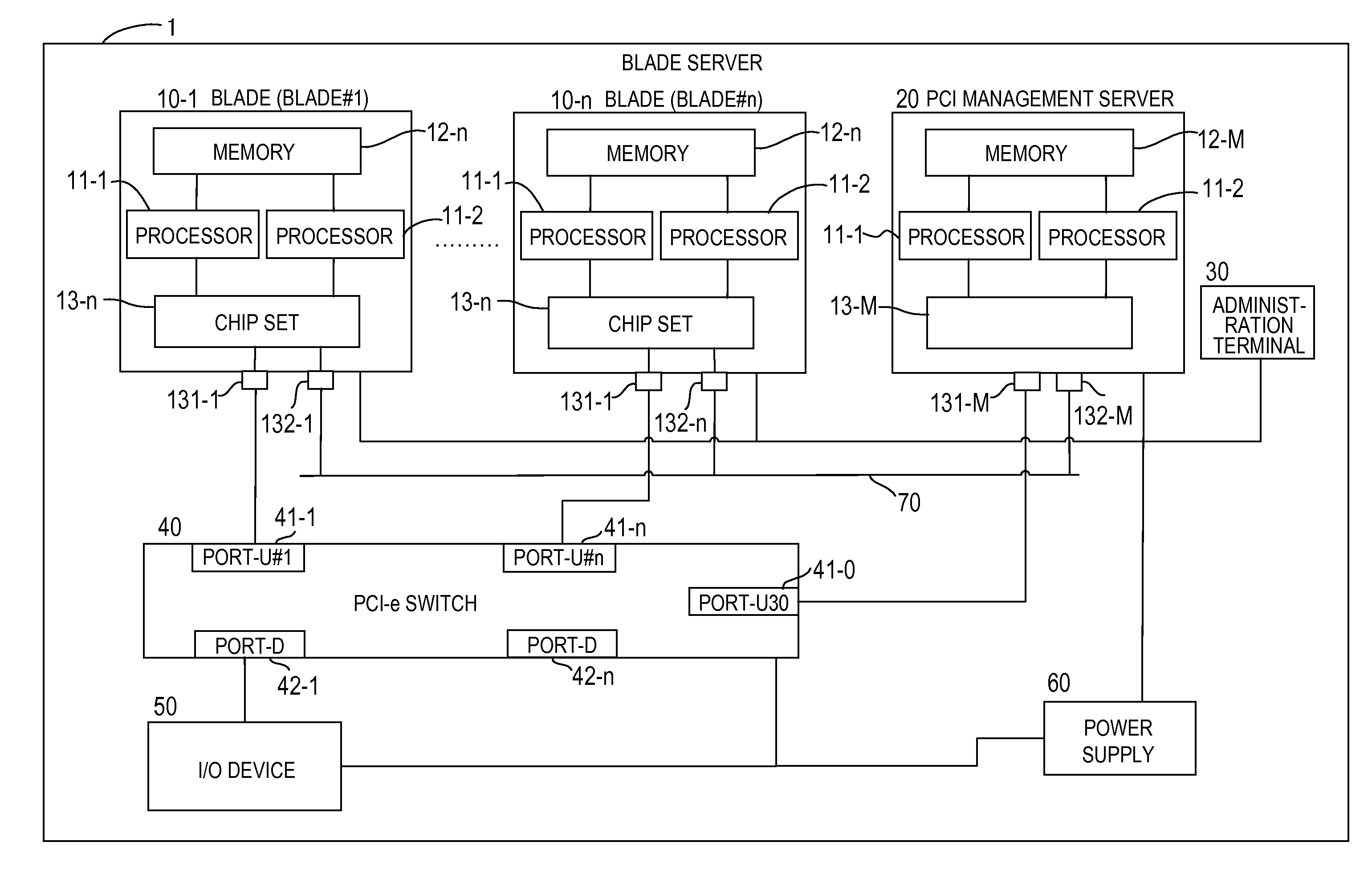
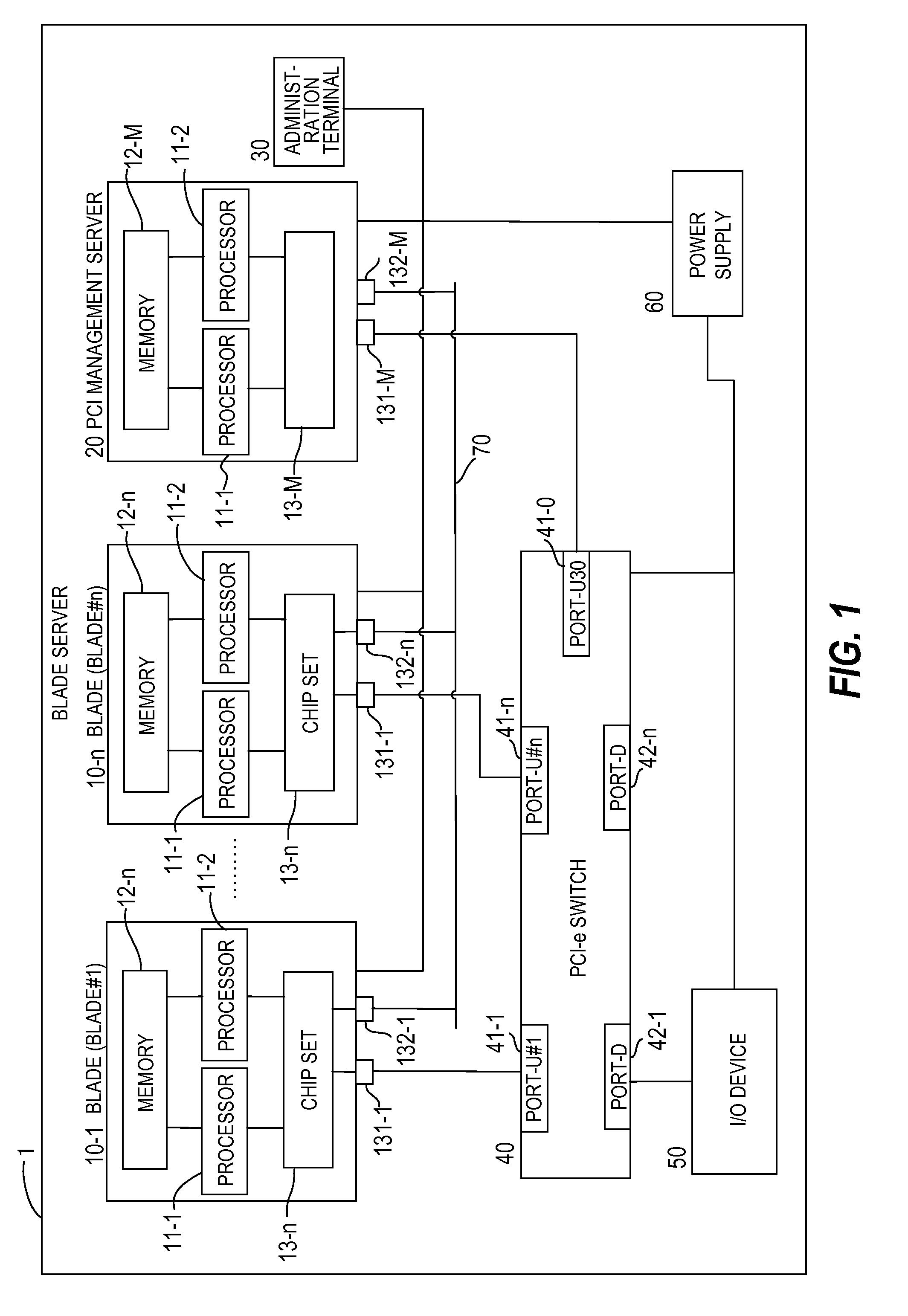
[0045]FIG. 1 illustrates an embodiment of this invention and is a block diagram of a blade server (compound computer system) to which this invention is applied. In FIG. 1, a blade server 1 includes n blades 10-1 to 10-n, which function as physical computers, an I / O device 50, which is compliant with Single Root IO Virtualization (hereinafter abbreviated as SR-IOV), a PCI-e switch 40, which couples the blades 10-1 to 10-n where transactions (packets) are processed by Multi Root IO Virtualization (hereinafter abbreviated as MR-IOV) with the I / O device 50, a PCI management server (PCI management computer) 20, which manages the allocation of the I / O device 50 to the blades 10-1 to 10-n, an administration terminal 30, which is operated by a user or an administrator to control the blade server 1, and a power supply 60, which supplies power to the components of the blade server 1. The PCI-e...


PUM


Abstract

In order to provide an inexpensive way to share an I / O device loaded in an I / O drawer among a plurality of blades, in a server system including a plurality of servers, a PCI device, and a manager for initializing a PCI switch, the PCI device has a plurality of virtual functions (VFs). The PCI switch, which has VF allocation information which indicates association between the servers and the VFs, is configured to: receive a transaction from one of the servers or from the PCI device; when the received transaction is a transaction sent from the one of the servers, remove a server identifier with which a sender server is identified and transfer the received transaction to the PCI device; and when the received transaction is a transaction sent from the PCI device, attach a server identifier that is determined based on the VF allocation information.

Description

CLAIM OF PRIORITY[0001]The present application claims priority from Japanese patent application JP2008-250208 filed on Sep. 28, 2008, the content of which is hereby incorporated by reference into this application.BACKGROUND OF THE INVENTION[0002]This invention relates to a blade server with a plurality of computers, and more particularly, to a technology of sharing a single I / O device among a plurality of computers.[0003]As people become more conscious of information security and information compliance, information systems of business organizations are demanded to process more processing requests such as virus scan and mail filtering on the server side. Business organizations have dealt with the increased processing requests by introducing a server for each different processing operation. However, an increase in server count increases running cost and cuts into the IT budget of a company to a degree that it poses a problem.[0004]In view of this problem, server integration is attract...

Claims


Application Information

Patent Timeline
Patent Type & Authority Applications(United States)
IPC IPC(8): G06F13/00
CPCG06F3/0227G06F13/387
Inventor BABA, TAKASHIGEMORIKI, TOSHIOMIUEHARA, KEITARO
Owner HITACHI LTD
Learn More