Planar sign geometry

a sign and geometry technology, applied in the field of planar signs, can solve the problems of saving the environmental cost of dealing with “disposable” materials, and achieve the effects of improving geometry, convenient reuse, and easy removal

Inactive Publication Date: 2010-04-08
SHIRLEY DAVID H +1
View PDF4 Cites 12 Cited by
  • Summary
  • Abstract
  • Description
  • Claims
  • Application Information

AI Technical Summary

Benefits of technology

[0006]The present invention addresses the shortcomings of prior planar card type signs used in o conjunction with a folding panel that either necessitate or encourage disposal of the folding panel or clip after a single use. The present invention is a planar card type sign having improved geometry that permits the card or sign to be inserted into an already folded sign holding device or clip and to be easily removed therefrom without prying the clip open. The closed clip remains positioned in the shelf channel ready for immediate reuse. The folding sign holding device or clip may therefore be easily reused because the geometry of the sign in the present invention is completely compatible for insertion in or removal from a closed clip. Also, the sign itself maybe reused if desired. It is not mutilated by removal from the closed clip. Reuse of existing clips, for any given promotion, or especially for various cumulative promotions results in very substantial cost savings. It also saves the environmental costs of dealing with “disposable” material that could have been continually reused. Use of the present invention for planar card type signs is extremely “application friendly”. Inserting the signs in the closed clips or disengaging the signs from the closed clips is a simple and fast activity for store personnel. Store personnel have time released for more important duties, such as keeping shelves stocked with product.

Problems solved by technology

It also saves the environmental costs of dealing with “disposable” material that could have been continually reused.

Method used


Image

  • Planar sign geometry
  • Planar sign geometry
  • Planar sign geometry

Examples


Embodiment Construction

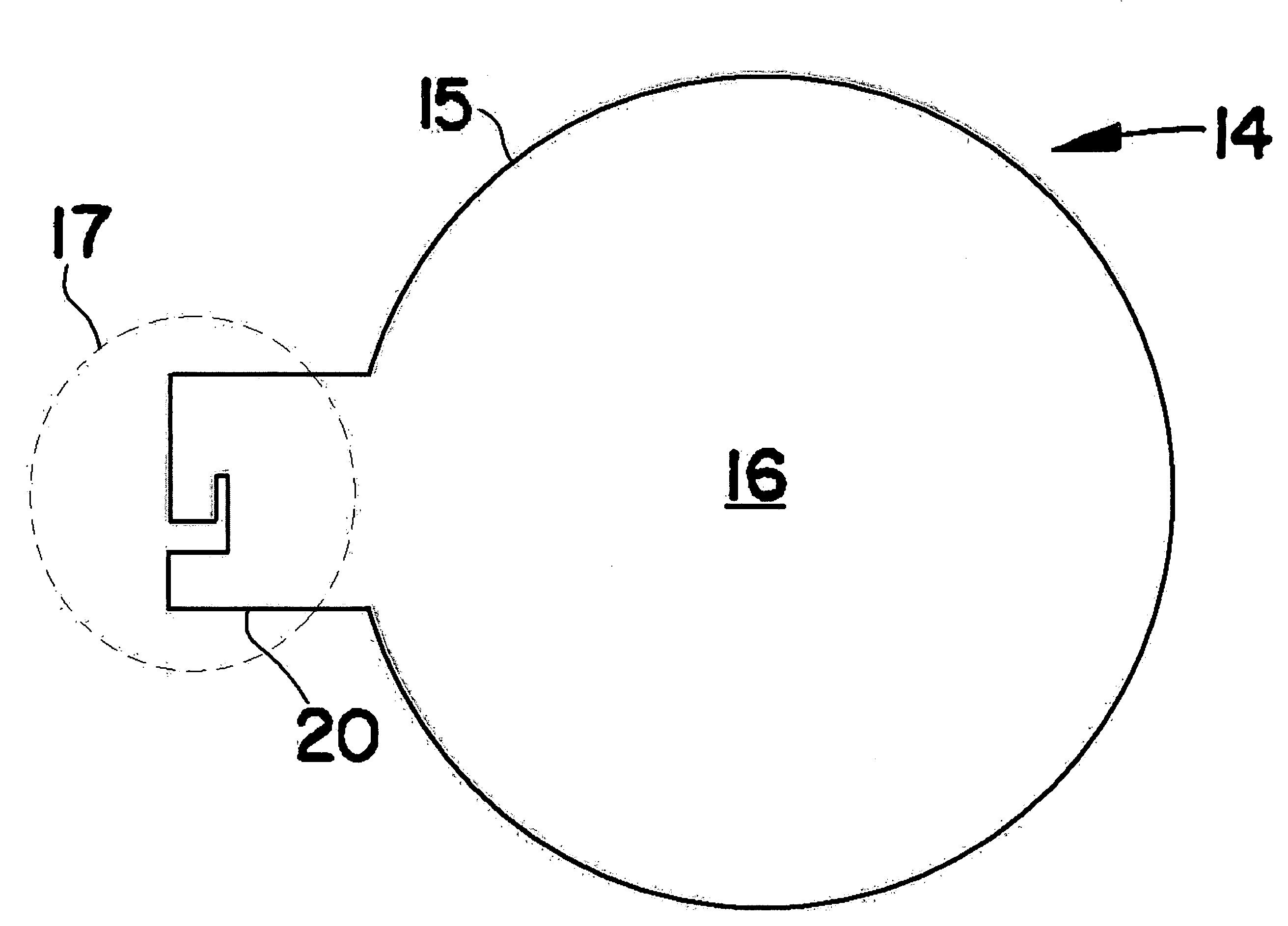
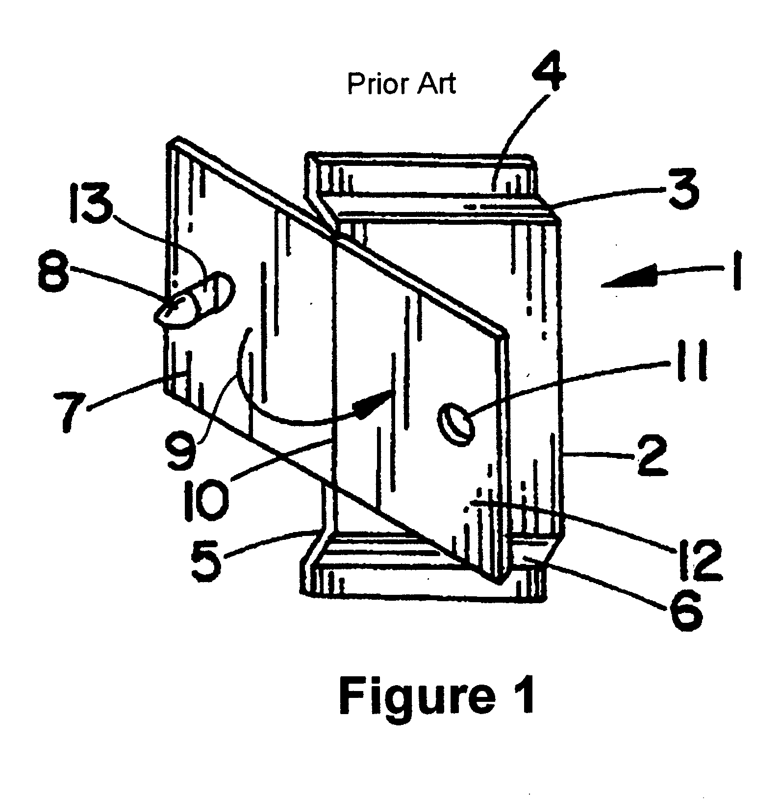
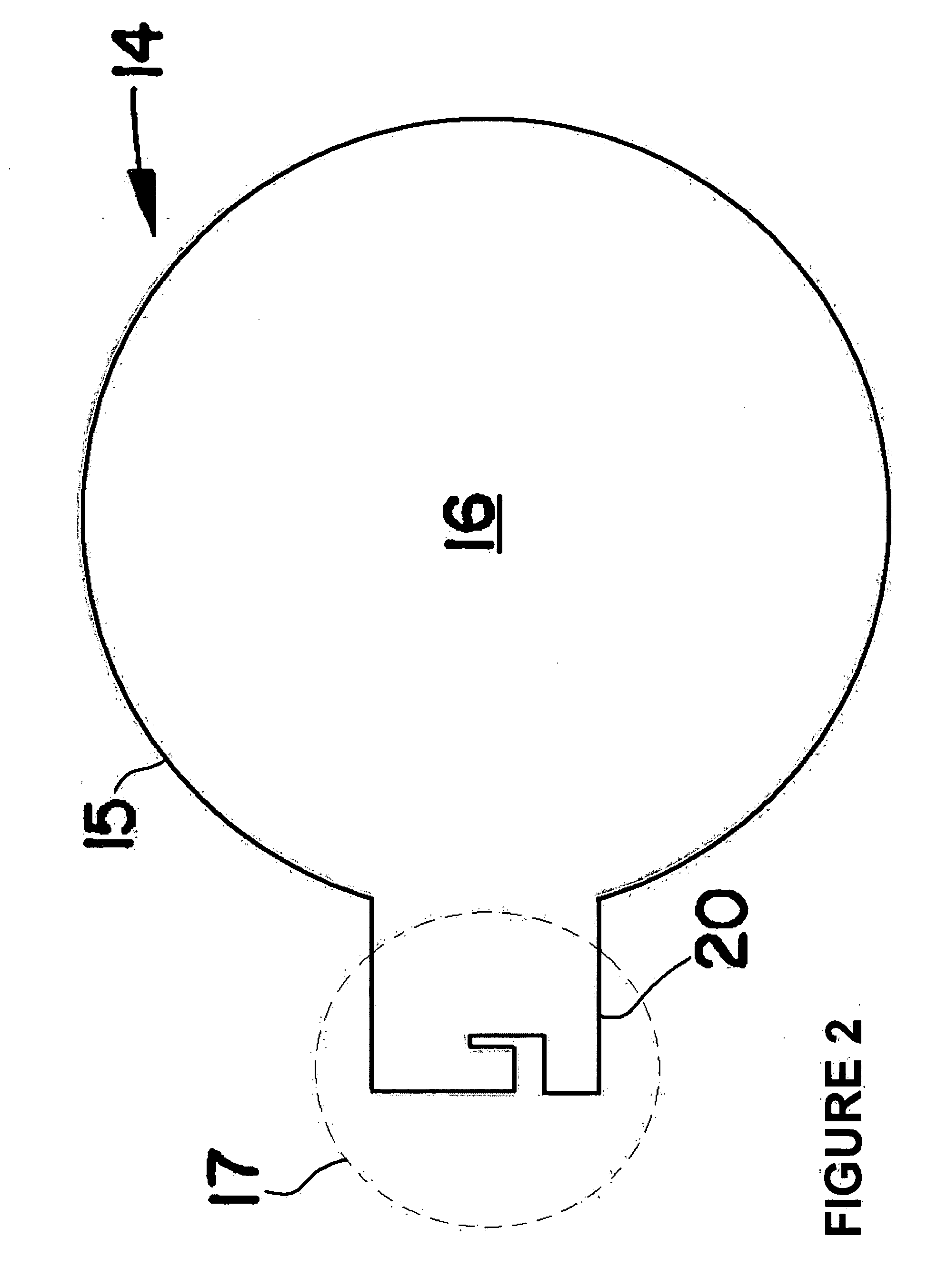
[0015]FIG. 1 illustrates a folding sign holder 1 which serves as a supporting and gripping surface for the planar sign 14 illustrated in FIG. 2. The folding sign holder 1 is mounted on a shelf channel 18 as illustrated in FIG. 4. The anchor arms 4 and 6 of the holder 1 are adapted to be retained within the channel 19 of shelf 18. While the sign shown has a generally circular perimeter 15, for example, the sign may be formed in any convenient shape including any common geometrical figure such as a square or rectangle, as well as any desired irregular or asymmetrical configuration. The sign 14 may be formed of any relatively rigid, thin material such as paper, Bristol board, cardboard, plastic or metal. The surface 16 is substantially planar and typically contains a message or graphic information that serves as an advertisement.

[0016]Planar sign 14 includes an integrally formed tab or channel region 20 which extends outwardly from the perimeter 15 of the sign. The tab 20 is adapted to...


PUM


Abstract

A planar sign (16) is retained by a sign holder (1) suitable for mounting on a shelf (18). The sign holder includes a prong (8) that fits within an orifice (11) so that the sign is gripped between panel 7 and the half 12, thereby securing the sign to the shelf 18. The sign includes a tab (20) that is formed with a series of edges (23, 25, 27, 29) that define a circuitous pathway leading to a radius (34) that prevents the further advance of the prong (8). By aligning the circuitous pathway of the sign (16) with the prong (8) and advancing the sign so as to guide the prong through the pathway, the sign may be inserted into the holder (1) even if the holder has been folded and the prong secured while previously used to hold a sign.

Description

FIELD OF THE INVENTION[0001]The present invention relates generally to planar signs, and more particularly to sign geometry that permits the reuse of a planar sign holder device or clip.BACKGROUND OF THE INVENTION[0002]Retail establishments frequently promote the sales of merchandise that is displayed and supported on shelves by means of promotional shelf signs that are affixed to the shelf channel by some sort of clip or holder device. The sign may be positioned in a plane that is either perpendicular or parallel to the front edge of the shelf in order to attract a potential purchaser's attention to the goods being offered.[0003]An example of a suitable sign holding clip is disclosed in U.S. Pat. No. 5,375,803, entitled HOLDER FOR PLANAR MATERIAL, issued on Dec. 27, 1994 to Kump. As shown in FIGS. 1, 6 and 7, the Kump holding device 1 is formed to include a panel 2 that has a first end edge 3 along which is supported a first anchor arm 4, as well as a second end edge 5 along which ...

Claims


Application Information

Patent Timeline
Patent Type & Authority Applications(United States)
IPC IPC(8): G09F7/00
CPCG09F1/10G09F2007/1856G09F7/18G09F3/204
Inventor SHIRLEY, DAVID H.O'NEIL, JOHN E.
Owner SHIRLEY DAVID H
Why Eureka
Try Eureka