Ferrite waveguide circulator with thermally-conductive dielectric attachments

a circulator and dielectric technology, applied in waveguide devices, basic electric elements, electrical apparatus, etc., can solve the problems of increasing the size and weight of the structure, reducing and limiting the application of ferrite structures to fixed-bias applications, so as to reduce the temperature rise of the ferrite and associated adhesive bonding. , the effect of improving the thermal conductivity of the path

Active Publication Date: 2010-03-23
EMS TECHNOLOGIES
View PDF37 Cites 20 Cited by
  • Summary
  • Abstract
  • Description
  • Claims
  • Application Information

AI Technical Summary

Benefits of technology

[0018]The present invention improves upon the geometry of conventional ferrite circulators in order to increase the average power handling and decrease the temperature rise in the ferrite and associated adhesive bondlines. Embodiments of the present invention utilize thermally conductive dielectric attachments on the sides of the ferrite element. These attachments significantly improve the thermal conductivity of the path from the ferrite element to the waveguide structure. If the attachments are good thermal conductors—such as, for example, boron nitride, aluminum nitride, or beryllium oxide—they can be relatively thin (for example, less than about 0.02″ thick for operations at about 20 GHz) to minimize the dielectric loading impact on RF performance while still improving the thermal performance of the circulator. Embodiments of the present invention decrease the maximum temperature of the ferrite element and associated bondlines, thus improving the performance and survivability of ferrite circulators in high power applications. Because of the increasing power handling capabilities in embodiments of the present invention, the ferrite circulators are suitable for a broader range of applications, making them a viable alternative to other switch technologies in high average power applications.

Problems solved by technology

This technique also relies on the presence of a significant gap or spacing between adjacent ferrite elements, increasing the size and weight of the structure.
However, these ferrite structures are restricted to fixed-bias applications with a single direction of circulation.
This opposing effect makes high power, broadband circulators difficult to achieve.

Method used


Image

  • Ferrite waveguide circulator with thermally-conductive dielectric attachments
  • Ferrite waveguide circulator with thermally-conductive dielectric attachments
  • Ferrite waveguide circulator with thermally-conductive dielectric attachments

Examples


Embodiment Construction

[0035]Reference will now be made in detail to the preferred embodiments of the invention, examples of which are illustrated in the accompanying drawings.

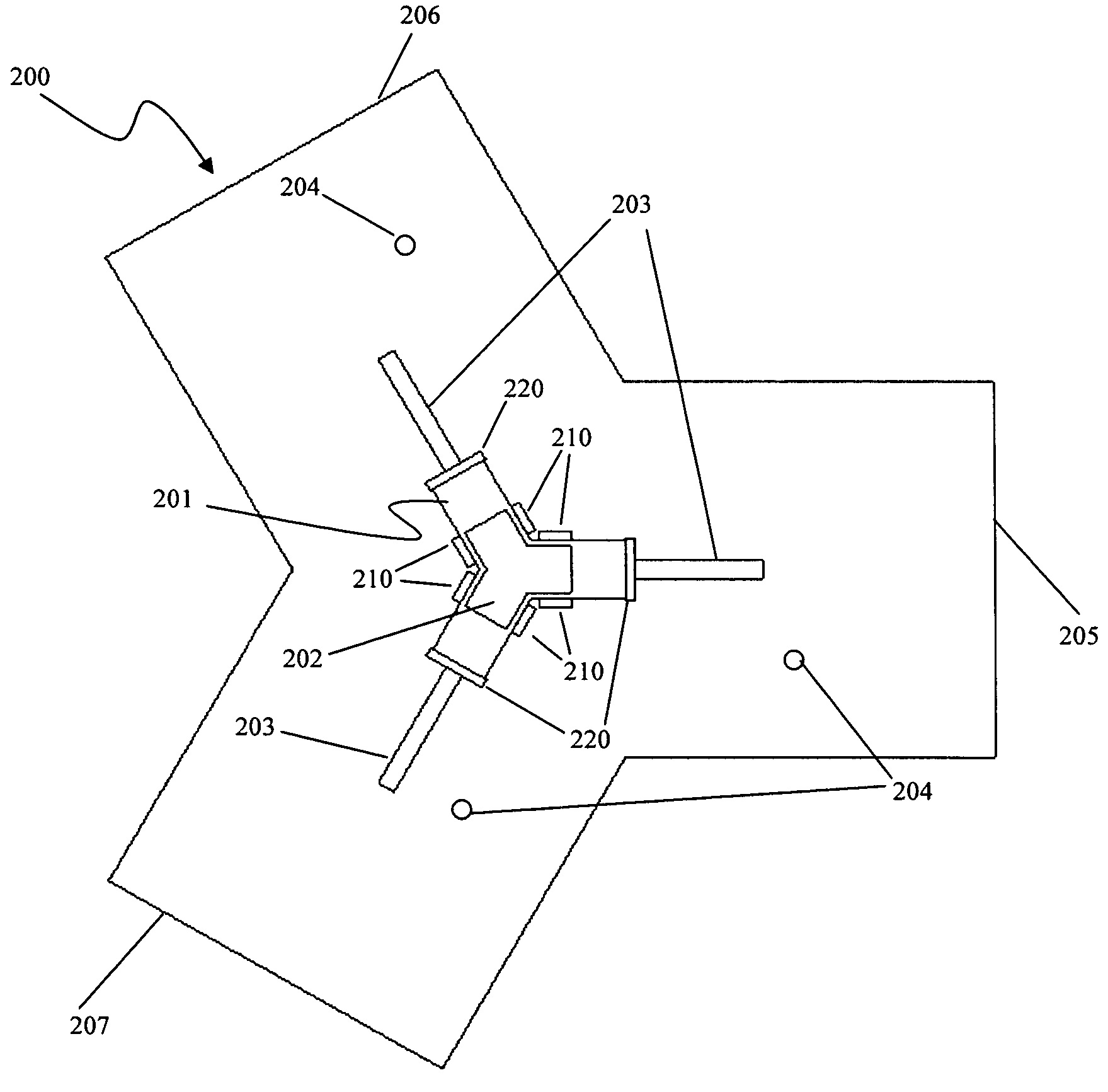
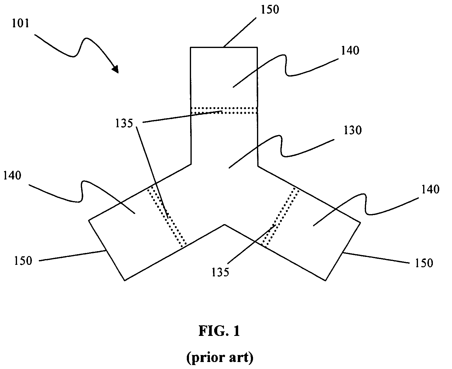
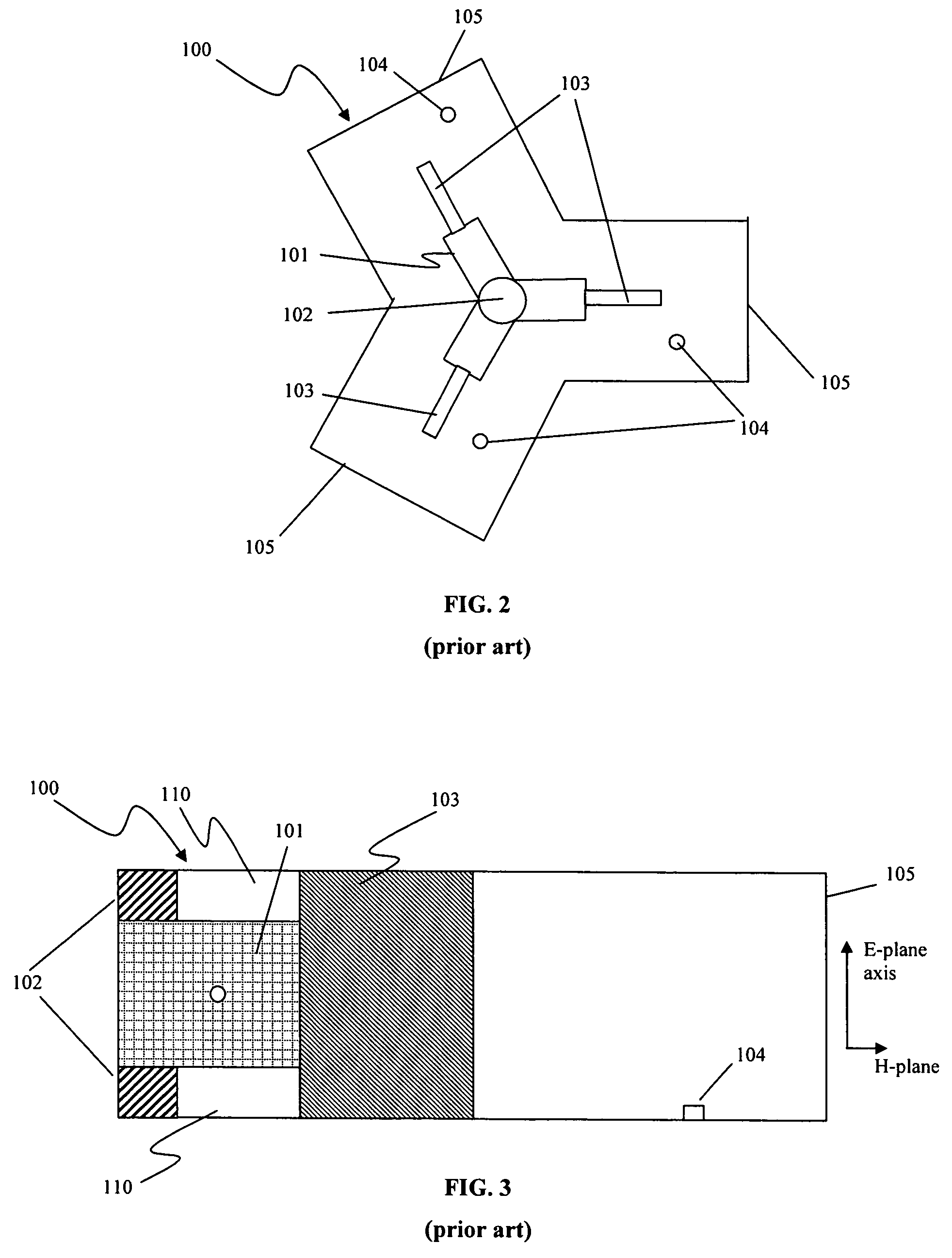
[0036]The embodiments of the present invention increase the average power handling over conventional ferrite circulators by decreasing the temperature rise in the ferrite and associated adhesive bonds. Due to the electrical and magnetic losses inherent in ferrite materials, the ferrite elements in circulators absorb a portion (generally around 2%) of the microwave power that passes through the devices. As ferrite is a relatively poor thermal conductor, the absorbed power results in high internal temperatures in the ferrite and the adhesives used to attach the ferrite to the traditional quarter-wave dielectric transformers and dielectric spacers. The high temperatures in the ferrite result in a degradation in performance, as the material properties of the ferrite change with temperature. The high temperatures in the adhesives can cau...


PUM

PropertyMeasurementUnit
relative dielectric constantsaaaaaaaaaa
length dimensionaaaaaaaaaa
height dimensionaaaaaaaaaa

Abstract

The present invention improves the geometry of ferrite circulators in order to increase the average power handling by decreasing the temperature rise in the ferrite and associated adhesive bonds. Embodiments of the present invention utilize dielectric attachments on the sides of the ferrite element, which maximizes the area of contact and minimizes the path length from the ferrite element out to the thermally conductive attachments.

Description

CROSS REFERENCE TO RELATED APPLICATIONS[0001]This application claims priority under 35 U.S.C. §119(e) from U.S. Provisional Patent Application No. 60 / 752,339, filed on Dec. 20, 2005, which is incorporated herein by reference.STATEMENT REGARDING FEDERALLY SPONSORED RESEARCH OR DEVELOPMENT[0002]Not ApplicableREFERENCE TO A “MICROFICHE APPENDIX”[0003]Not ApplicableBACKGROUND OF THE INVENTION[0004]1. Field of the Invention[0005]The present invention relates to waveguide circulators, and more particularly to improved power handling capabilities for ferrite waveguide circulators through the use of thermally-conductive dielectric attachments.[0006]2. Description of the Related Art[0007]Ferrite circulators have a wide variety of uses in commercial and military, space and terrestrial, and low and high power applications. A waveguide circulator may be implemented in a variety of applications, including but not limited to transmit / receive (T / R) modules, isolators for high power sources, and sw...

Claims


Application Information

Patent Timeline
Patent Type & Authority Patents(United States)
IPC IPC(8): H01P1/39
CPCH01P1/39
Inventor KROENING, ADAM M.
Owner EMS TECHNOLOGIES
Why Eureka
Try Eureka