
Environmental brush seal

a brush seal and environmental technology, applied in mechanical equipment, special door/window arrangements, transportation and packaging, etc., can solve the problems of air infiltration in most buildings, significant additional energy costs, etc., and achieve the effect of effective environmental seal, reduced gas flow in use, and increased pressur

Inactive Publication Date: 2010-04-08
MATTICE DOUGLAS A
View PDF46 Cites 12 Cited by
  • Summary
  • Abstract
  • Description
  • Claims
  • Application Information

AI Technical Summary

Benefits of technology

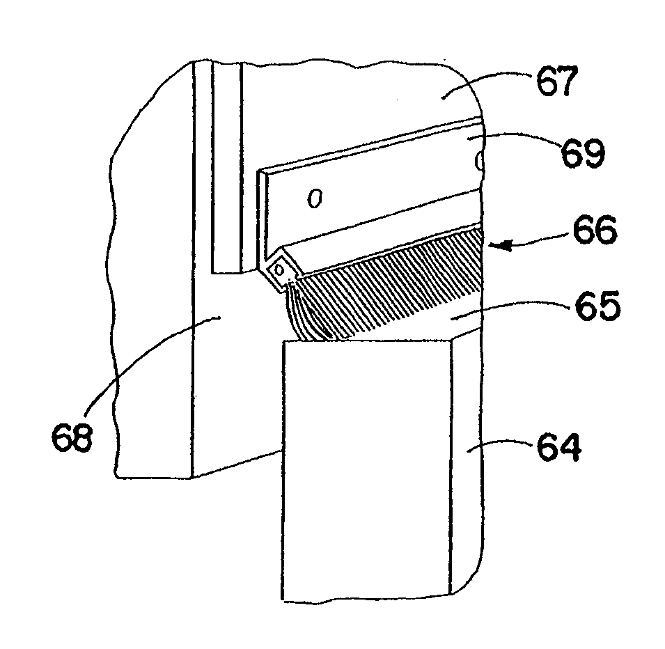
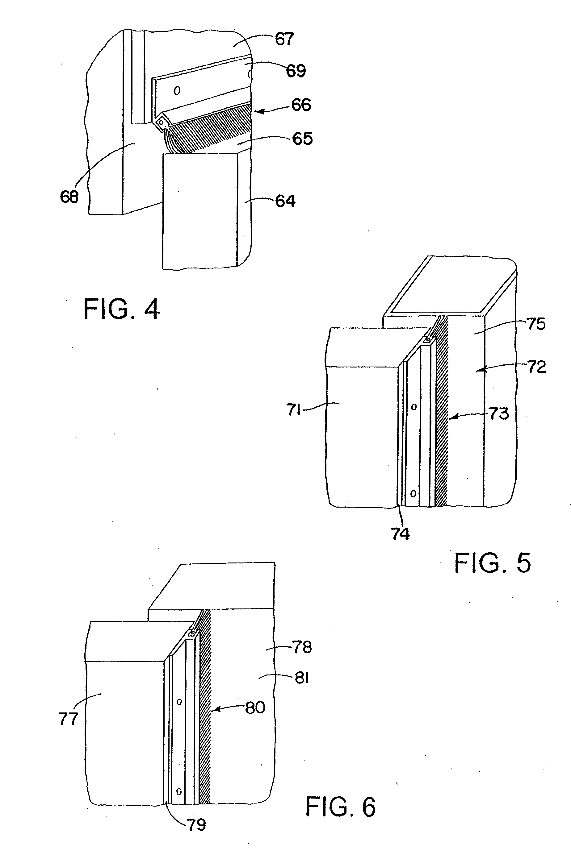
[0007]It has been discovered that a more effective environmental seal is obtained if the filaments are triangular in transverse section, and of such a shape that the filaments when not separated will nest with each other to form a barrier or wall without significant pockets or separations. The relatively sharp acute angle corners of the filaments, which inter-fit or interlock, require greater pressures to force the filaments apart. More rounded less sharp corners are more easily forced apart or twisted past one another to create openings or gaps for smoke or gases to pass through. Substantially isosceles or equilateral triangular filaments form a tighter barrier. They substantially reduce gas flow in use when compared to conventional filaments.
[0008]The acute angled corners of the filaments are more effective than the typical cylindrical or round filament since the angled corners tend to create turbulence in the form of eddies or vortices as air tries to move past the filaments from an area of higher pressure to that of lower pressure reducing the force on the filaments.
[0010]To reduce or eliminate the passing of these gasses and smoke through the openings of these closed elevator doors, several devices have been designed to restrict the openings in these doors. Examples of these devices include assemblies disclosed in U.S. Pat. No. 5,383,510 issued Jan. 24, 1995, U.S. Pat. No. 5,195,594 issued Mar. 23, 1993, and U.S. Pat. No. 5,836,424 issue dated Nov. 17, 1998.
[0011]Computer rooms and other rooms which are environmentally controlled for manufacturing processes often have passages through the floors or walls to provide access for cables, or in walls between rooms for the passage of utilities or materials between rooms. These openings often permit undesired flow of air (smoke, fumes, dust, etc.) between those rooms and cause unwanted contamination, or higher load air cleaning or conditioning requirements. The triangular filaments used in the device provide easy passage of materials or cables through the filaments, and yet their triangular shape provides greater resistance to undesired air flow than the commonly used round filaments.

Problems solved by technology

Air infiltration is a problem in most buildings.
Not only is it costly, but for the people who live or work in a drafty environment it can be uncomfortable as well.
The problem with air infiltration is that in the summer heat enters a building through small gaps around openings.
Over the course of a year, the additional energy costs are significant.
Brush weatherseals have a significant environmental and energy impact and allow significantly less air leakage than vinyl seals.

Method used


Image

  • Environmental brush seal
  • Environmental brush seal
  • Environmental brush seal

Examples


Embodiment Construction

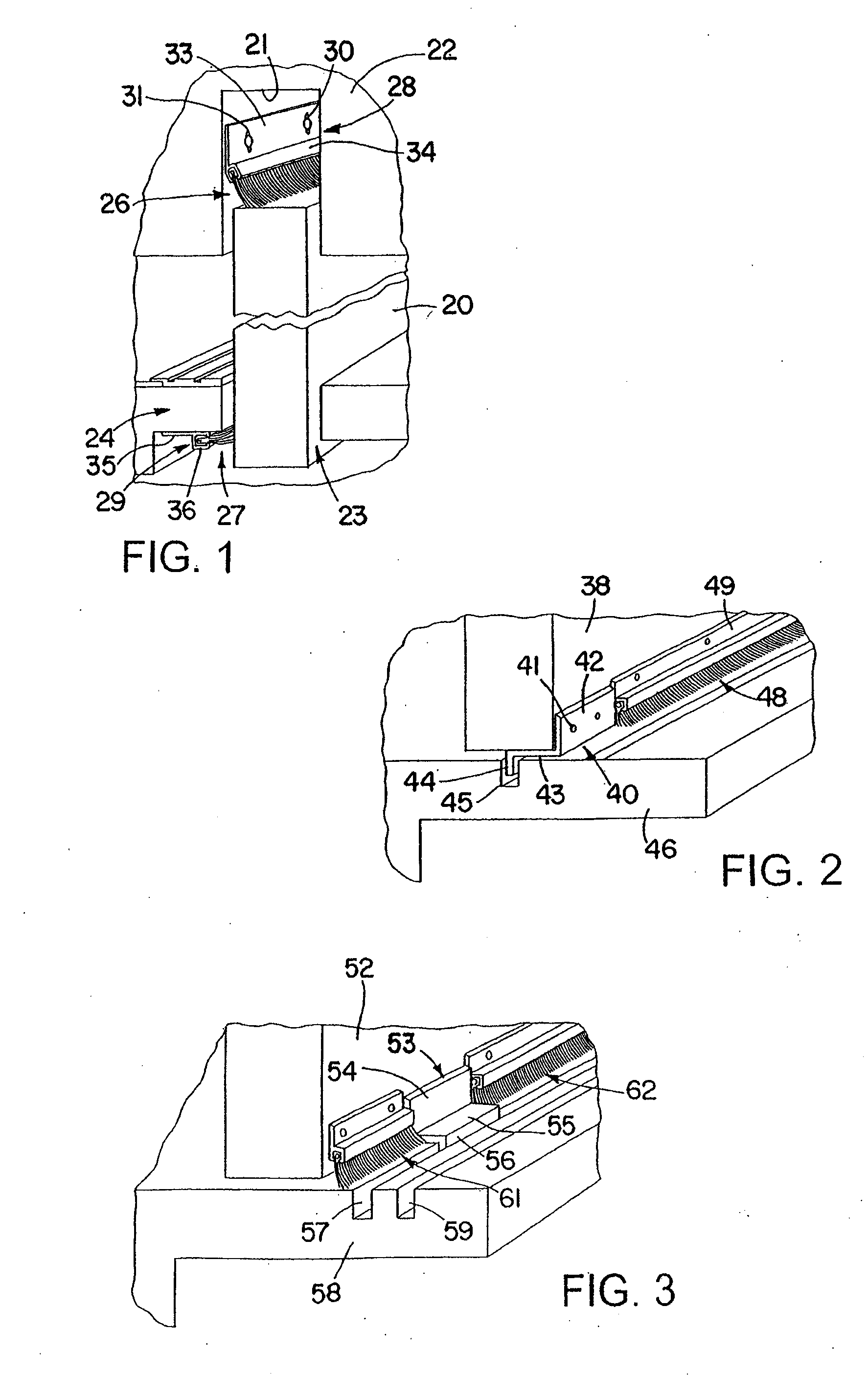
[0029]Referring first to FIG. 1 there is illustrated an elevator door at 20 which projects into a slot 21 in header 22 and also rides in slot 23 in sill 24. The door slides toward and away from the viewer within the header and sill slots. The door is of course shown broken away foreshortening its vertical height. The typical roller-track structure and actuator are not shown.

[0030]In FIG. 1, two environmental seals in accordance with the invention are shown, one at 26 within the header slot 21, and the other at 27 within the sill slot 23. The seals are in the form of strip brushes hereinafter described which slide into the channels of aluminum extruded holders shown at 28 and 29, respectively, held to the structures by fasteners shown at 30 which extend through elongated slots 31 permitting the holder to be adjusted toward and away from the moving door. It is noted that the assembly of FIG. 1 shows two different types of holders. At the top the holder has an angled flange 33 extendin...


PUM


Abstract

A passive brush seal effectively to limit conditioned air such as humidity, temperature or filtered air, or contaminated air such as smoke or fumes from an area of greater pressure to one of lower pressure. The passive brush seal is in the form of a strip brush with triangular filaments that provide an improved block to the flow of gases. The shape of the filaments is such that they inter-fit or interlock and separate less readily. Important applications are as elevator seals or clean room or computer room seals.

Description

CROSS-REFERENCE TO RELATED APPLICATION[0001]This application is a continuation-in-part application of U.S. application Ser. No. 11 / 820,118, filed Jun. 18, 2007.DISCLOSURE [0002]This invention relates generally as indicated to an environmental brush seal, and more particularly to a strip brush passive seal or barrier shield for protecting or isolating environments such as elevator shafts, clean rooms, computer rooms, or other gaps or closures where pressure differentials may exist.BACKGROUND OF THE INVENTION[0003]Air infiltration is a problem in most buildings. Not only is it costly, but for the people who live or work in a drafty environment it can be uncomfortable as well. The problem with air infiltration is that in the summer heat enters a building through small gaps around openings. Of course, air conditioned air escapes from these same openings. In the winter, this problem is compounded by a phenomenom known as “chimney” or “stack” effect. Essentially, hot air rises and escapes...

Claims


Application Information

Patent Timeline
Patent Type & Authority Applications(United States)
IPC IPC(8): E06B7/16F16J15/02
CPCB66B13/308H02G3/22F16J15/3288E06B7/22
Inventor MATTICE, DOUGLAS A.
Owner MATTICE DOUGLAS A
Learn More