Jewelry assembly

Inactive Publication Date: 2010-04-08
HATTON DESIGNS OF LONDON
View PDF15 Cites 8 Cited by
  • Summary
  • Abstract
  • Description
  • Claims
  • Application Information

AI Technical Summary

Benefits of technology

[0031]The system taught herein, by providing the rounded mechanical locking elements, is able to provide mechanical locking elements which can be discreetly placed on even very thin or small support elements and small collets to provide a reliable holding effect before the assembly is finally fixed.
[0032]An advantage of the provision of the mechanical locking elements as a ball-shaped (i.e. substantially semi-spherical) protrusion and a corresponding ball-shaped (i.e. substantially semi-spherical) recess, is that the protrusion tends to roll into the recess as the collet and shank are placed together. This means that the locking elements are easy to engage, but also means that the elements are more tolerant to a slight discrepancy in their manufa

Problems solved by technology

However, owing to the shape of the collet, it is difficult to hold the components in the correct position for the soldering process.
In order to perform the above mentioned procedure, considerable jeweller time and skill is required to place and clamp the collet in the correct orientation with respect to the shank.
If the collet is designed to accept a diamond or other precious stone to make a high quality and expensive item of jewelry, the slightest imperfection can result in rejection of the entire item of jewelry.
The inadequacy of clamping can also lead to unwanted gaps if the collet and the shank are misaligned, or if the collet and the shank do not fit precisely.
Accordingly, if it is not clamped in the correct position, the application of solder to secure the collet to the shank can result in an imperfect article that cannot be corrected.
This inevitably leads to significant wastage and lower production yield.
The wastage in terms of materials as well as time caused by these problems inevitably increases the cost of production.
In addition to the problem of aligning the collet and shank before applying solder, there is the additional problem that the clamping of the collet to the shank will not be sufficient to prevent the components from moving or rotating with respect to each other as the solder is applied.
Accordingly, considerable expertise and professional time is required, but even this can not remove the possibility of errors

Method used


Image

  • Jewelry assembly
  • Jewelry assembly
  • Jewelry assembly

Examples


Embodiment Construction

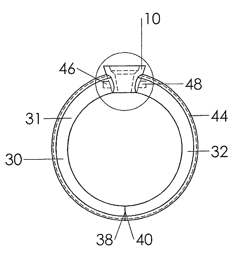
[0122]In the following description, examples and embodiments will be described assuming that each of the components is in the orientation as it would be in a ring assembly which is orientated such that a collet is at the top of a shank. However, this is done for facility of description only, the relations between the components being equivalent in any other orientation.

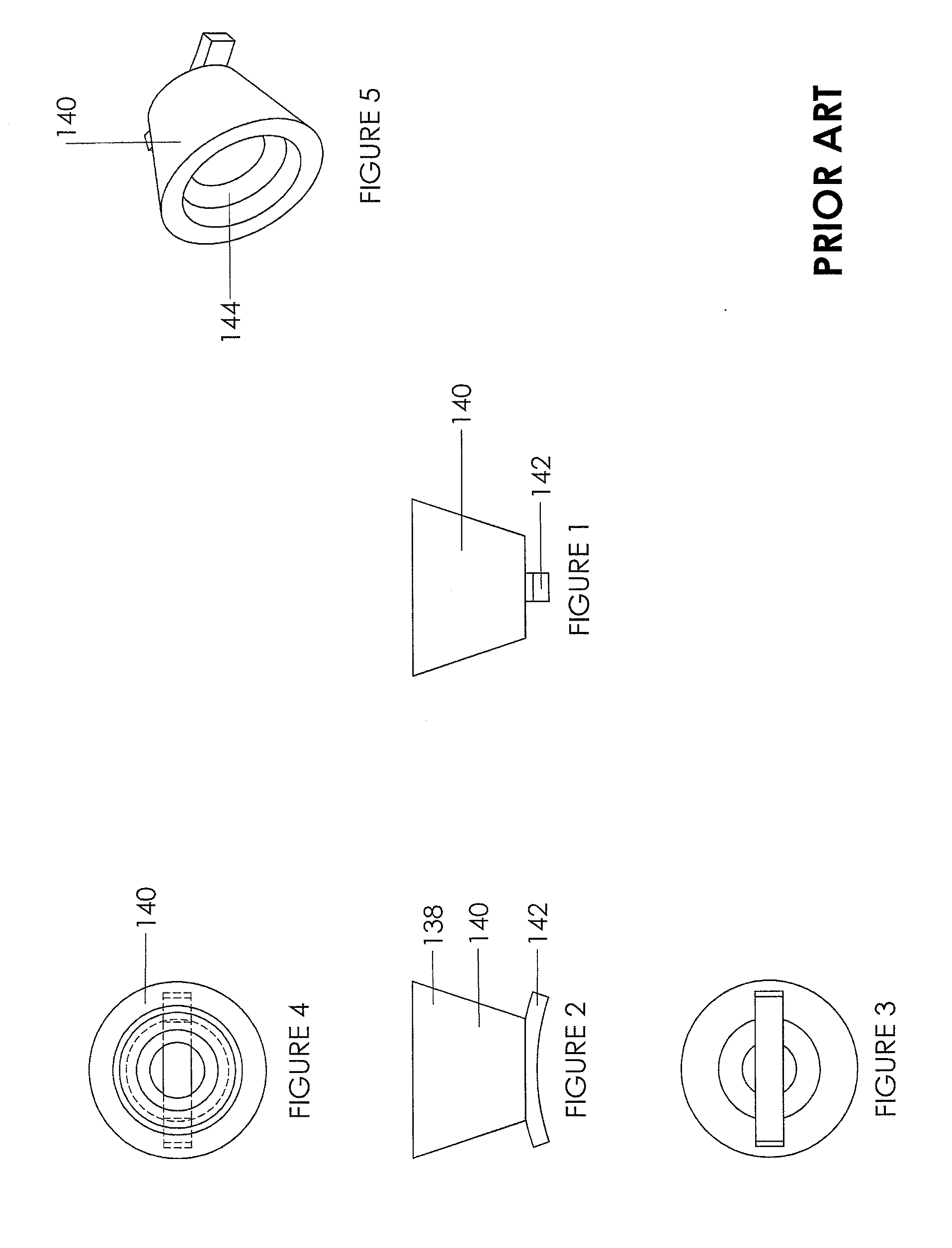
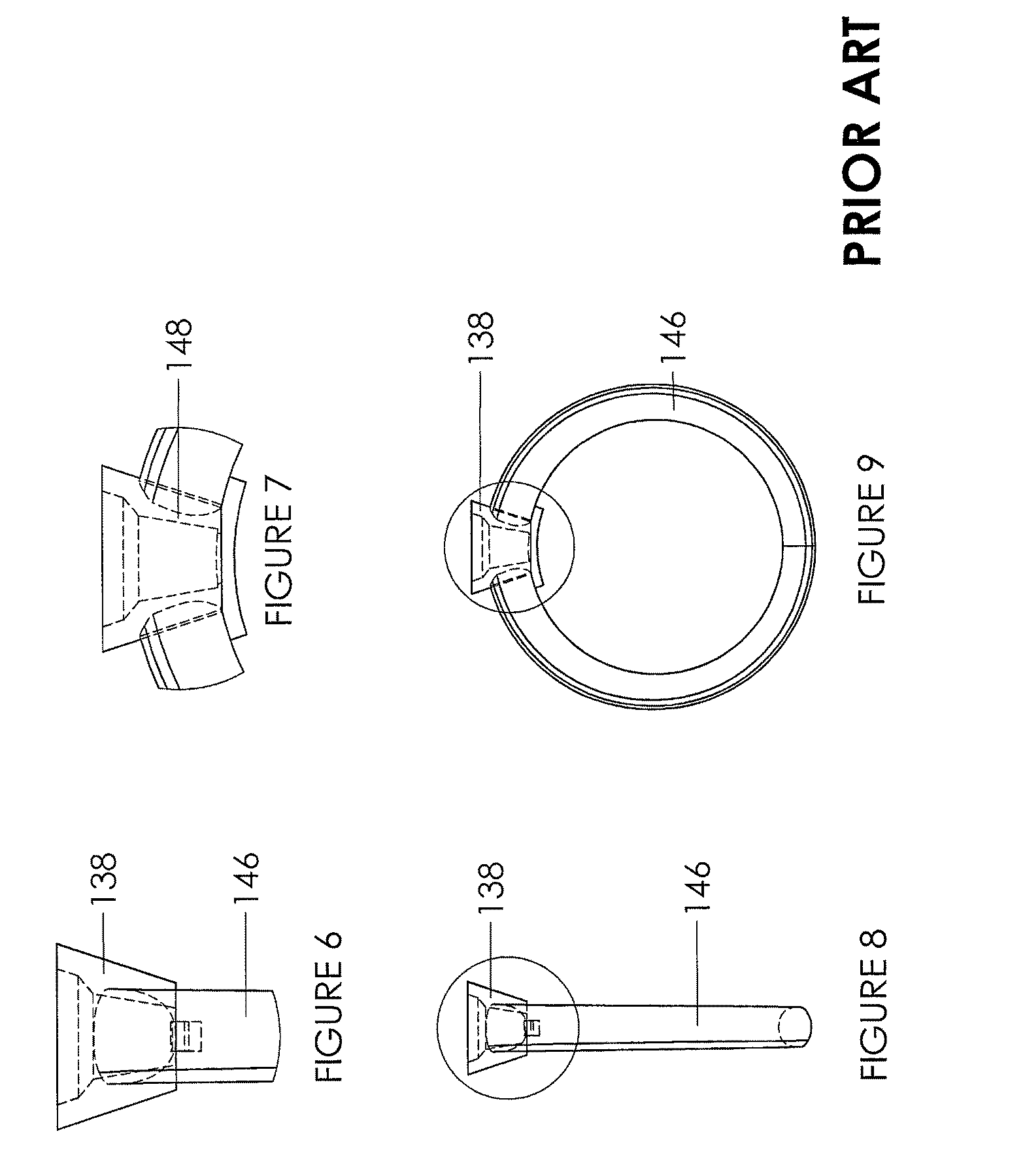
[0123]FIGS. 1 to 9 depict a prior art arrangement example, in which FIGS. 1 to 5 depict a collet 138 and FIGS. 6 to 9 depict a ring assembly incorporating the collet 138 according to FIGS. 1 to 5.

[0124]The collet 138 comprises a substantially frusto-conical body 140 and a support bar 142. The collet body 140 is provided with a displaced internal shelf 144 for accepting a jewel stone or precious metal. The support bar 142 substantially follows the arc of a circle and is formed below the base of the collet 138.

[0125]The shank 146 is a substantially annular member provided with a gap 148 in which the collet 138 can sit s...


PUM

PropertyMeasurementUnit
Mechanical propertiesaaaaaaaaaa

Abstract

A jewelry assembly comprises a shank (30, 70, 110, 156, 172, 198) and a collet (10, 50, 108, 150, 164, 186) and a locking element (26, 28, 46, 48, 64, 66, 92, 94, 105, 107, 152, 162, 166, 170, 182, 184, 196, 202) on each of the collet (10, 50, 108, 150, 164, 186) and shank (30, 70, 110, 156, 172, 198) arranged to mechanically cooperate to hold the collet (10, 50, 108, 150, 164, 186) and shank (30, 70, 110, 156, 172, 198) in a predetermined relative position. Two locking elements (26, 28, 46, 48, 64, 66, 92, 94, 105, 107, 152, 162, 166, 170, 182, 184, 196, 202) may be provided on each side of the collet which are rounded protrusions and which cooperate with corresponding holes in the shank.

Description

TECHNICAL FIELD [0001]The present invention relates to jewelry assemblies and methods of manufacturing jewelry assemblies.BACKGROUND OF THE INVENTION [0002]Jewelry assemblies, such as ring assemblies, are commonly formed by casting a collet and a shank separately. The collet and the shank are generally moulded from different materials. For example, the collet may be moulded from 18 ct white gold and the shank from 18 ct yellow gold. In order to provide a finished assembly, the collet and the shank need to be held in a predetermined relative position and fixed together for example by soldering. However, owing to the shape of the collet, it is difficult to hold the components in the correct position for the soldering process.[0003]In the prior art, the base of the collet is generally provided with a support bar which provides an extension on either side of the base of the collet and which can rest against the inner circumference of the shank. The support bar can then be used to clamp ...

Claims


Application Information

Patent Timeline
IPC IPC(8): A44C5/00A44C27/00
CPCY10T29/49593A44C17/02A44C9/00A44C17/0208
Inventor JOSEPH, URIELJOSEPH, YONITHAN
Owner HATTON DESIGNS OF LONDON
Why Eureka
Try Eureka