Pneumatic tire

a technology of pneumatic tires and tires, applied in the field of pneumatic tires, to achieve the effect of reducing the rolling resistance of tires, reducing the range of optimizing the groove area ratios g

Active Publication Date: 2010-04-08
THE YOKOHAMA RUBBER CO LTD
View PDF14 Cites 5 Cited by
  • Summary
  • Abstract
  • Description
  • Claims
  • Application Information

AI Technical Summary

Benefits of technology

[0034]In a pneumatic tire according to the present invention, (1) provided that a groove area ratio for a wear rate 0% is Gs, and a groove area ratio for a wear rate 100% is Ge, a difference Gs-Ge falls in a predetermined range. Thus, the reduction in the groove area ratio G is optimized from when the tire is new to when the tire is in the last stage of wearing. This ensures the reduction range of the groove area ratio G appropriately, providing an advantage of reducing the tire rolling resistance. Further, (2) the groove area ratio G for a wear rate 20% and the groove area ratio G for a wear rate 35% fall in predetermined ranges of (Gs-G) / (Gs-Ge). Thus, the reduction in the groove area ratio G is optimized in the early stage of wearing. This ensures the stiffness of the block arrays in the early stage of wearing, providing an advantage of reducing the tire rolling resistance from the early stage of wearing.

Problems solved by technology

Pneumatic tires with a traction pattern have challenges to maintain snow braking and wet performance of the tire.

Method used


Image

  • Pneumatic tire
  • Pneumatic tire
  • Pneumatic tire

Examples


embodiment

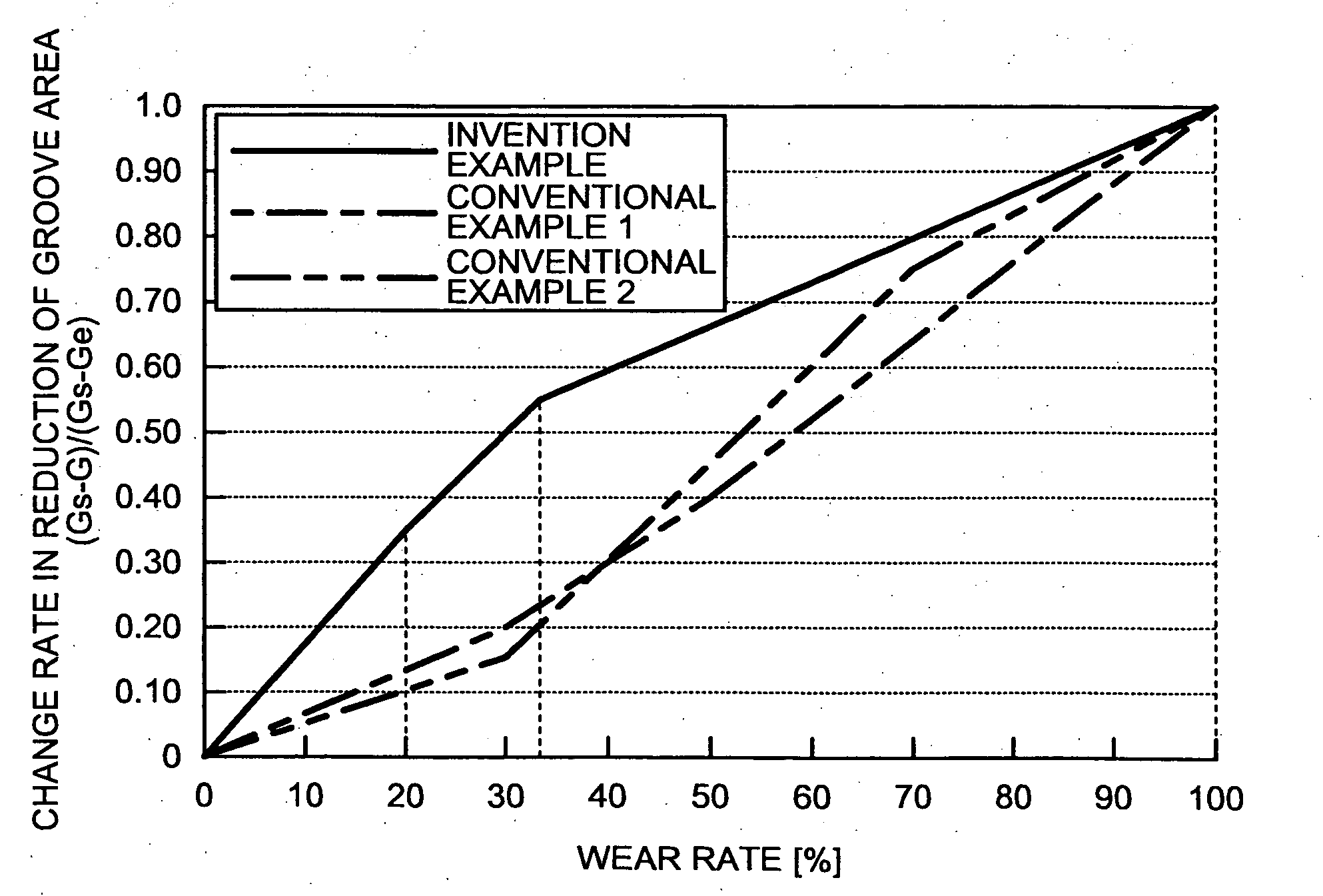
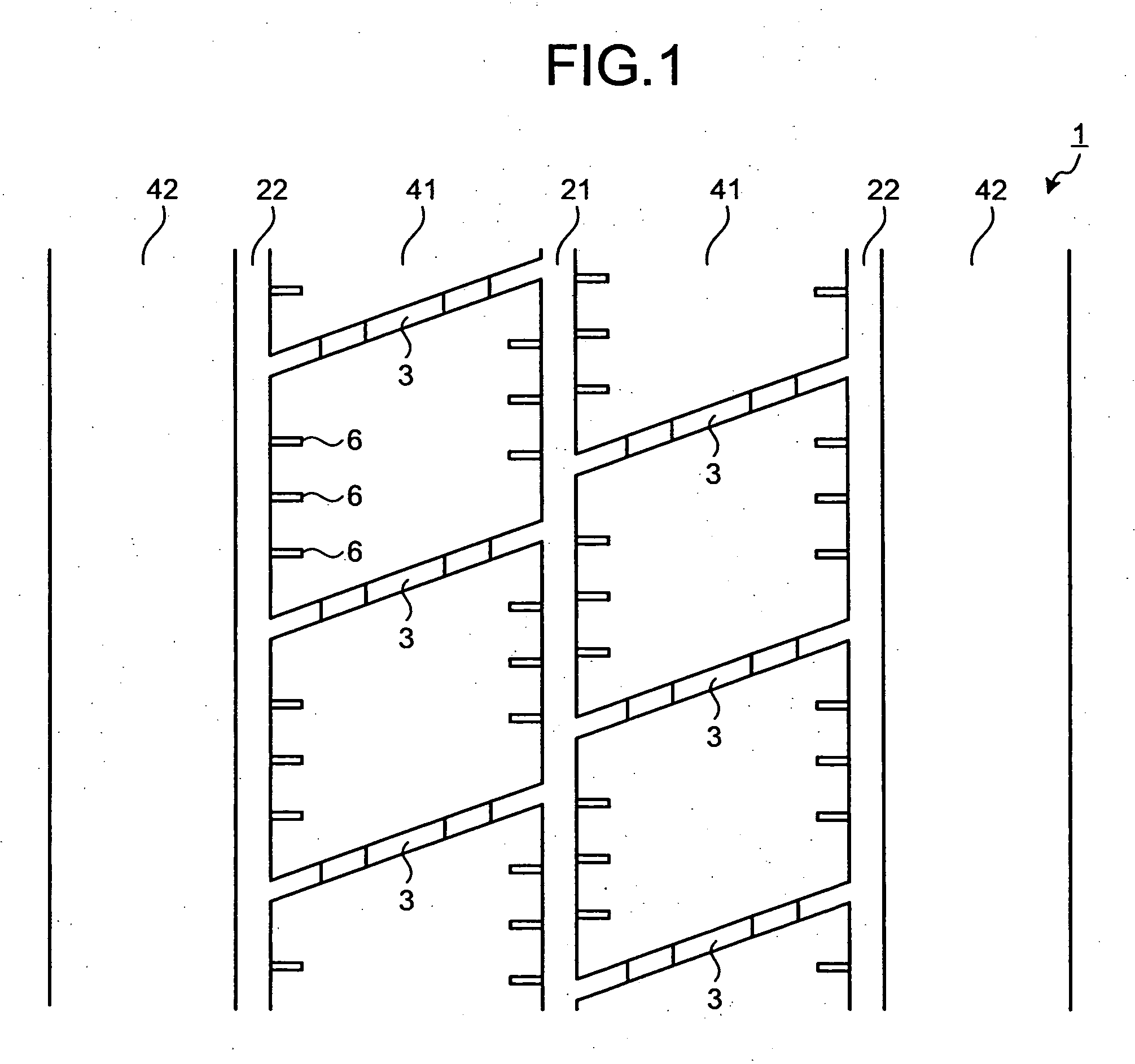
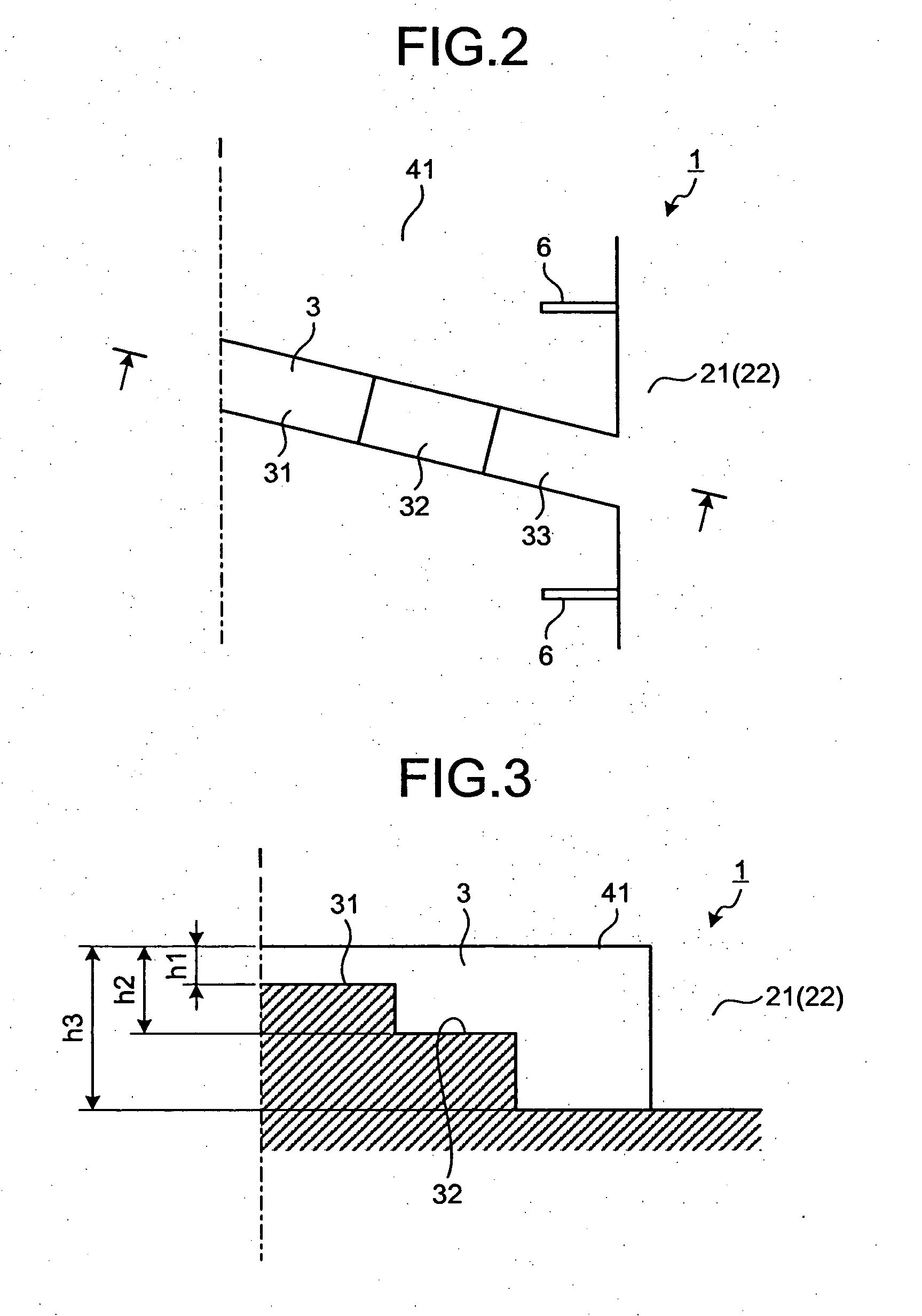
[0059]FIG. 1 is a plan view of a tread of a pneumatic tire according to an embodiment of the present invention. FIGS. 2 and 3 are a plan view (FIG. 2) and a cross-sectional view (FIG. 3) of a widthwise groove of the pneumatic tire shown in FIG. 1. FIGS. 4 and 5 are graphs for explaining performance of the pneumatic tire shown in FIG. 1. FIGS. 6 to 12 are explanatory views of modifications of the pneumatic tire shown in FIG. 1. FIG. 13 is a table indicating performance test results of the pneumatic tire according to the embodiment of the present invention.

[0060]Pneumatic Tire

[0061]A pneumatic tire 1 has a tread that includes: at least three circumferential main grooves 21 and 22 extending in a tire circumference direction; a plurality of widthwise grooves 3 extending in a tire width direction; and a plurality of block arrays 41 segmented by the circumferential main grooves 21 and 22 and the widthwise grooves 3 (see FIG. 1). With this arrangement, a traction pattern is formed based on...


PUM


Abstract

In a pneumatic tire, a difference Gs-Ge falls in a range of Gs-Ge≧0.10, where Gs is a groove area ratio for a wear rate 0% and Ge is a groove area ratio for a wear rate 100%. Further, a groove area ratio G for a wear rate 20% falls in a range of (Gs-G)/(Gs-Ge)≧0.30, and a groove area ratio G for a wear rate 35% falls in a range of (Gs-G)/(Gs-Ge)≧0.50.

Description

TECHNICAL FIELD[0001]The present invention relates to a pneumatic tire. The invention particularly relates to a pneumatic tire that achieves improved tire rolling resistance, while maintaining snow braking and wet performance.BACKGROUND ART[0002]Pneumatic tires in recent years have widthwise grooves arranged in center and shoulder areas of a tread to ensure their braking and driving performance. Such a tread pattern is called a traction pattern. Pneumatic tires with a traction pattern have challenges to maintain snow braking and wet performance of the tire. Further, such pneumatic tires tend to have an increased tire rolling resistance due to a large number of widthwise grooves arranged thereon.[0003]Patent Document 1 discloses a known technology of a conventional pneumatic tire that is related to the present invention. The conventional pneumatic tire has wide grooves including a pair of main grooves that are provided on its tread outer surface to be away from an equatorial plane th...

Claims


Application Information

Patent Timeline
Patent Type & Authority Applications(United States)
IPC IPC(8): B60C11/03
CPCB60C11/01B60C11/0309B60C11/12B60C11/13B60C11/1369Y10S152/03B60C11/1236B60C11/1315B60C2011/0348B60C2011/0397B60C11/033Y02T10/86
Inventor KOUTOKU, KOUICHI
Owner THE YOKOHAMA RUBBER CO LTD
Why Eureka
Try Eureka