
System for producing energy through the action of wind

Inactive Publication Date: 2010-04-08
BEANE GLENN L
View PDF30 Cites 2 Cited by
  • Summary
  • Abstract
  • Description
  • Claims
  • Application Information

AI Technical Summary

Benefits of technology

[0007]The wind guide system assists in directing the air flow towards the wind engaging panels while limiting air flow from engaging all the panels at the same time.
[0014]In an embodiment, the wind engaging panels extend to a point near the horizontal shaft defining a gap between the panel and the shaft to allow air flow on all sides of the panel therein creating a low pressure area behind the panel to assist in the movement of the panel.
[0016]The wind guide system assists in directing the air flow towards the wind engaging panels while limiting air flow from engaging all the panels at the same time.

Problems solved by technology

Unfortunately, prior attempts to produce electrical power from wind have failed to appreciate the benefits of ground effect.
Furthermore, some systems have complicated the structures by requiring massive support structures and complicated gearing.

Method used


Image

  • System for producing energy through the action of wind
  • System for producing energy through the action of wind
  • System for producing energy through the action of wind

Examples


Embodiment Construction

[0033]There are numerous factors that cause the movement of air or wind. These factors include differential heating between the equator and the poles and the rotation of the planet.

[0034]A system and method of generating energy by transforming energy from a low-density substance, such as air flow or wind, into kinetic energy by directing the flow through a wind guide system towards panels that rotate in generally the same directions as the air flow. Furthermore, the system uses the ground and / or water as a surface for guiding the air flow towards the windmill devices. The wind guide system also limits air flow from engaging all the panels at the same.

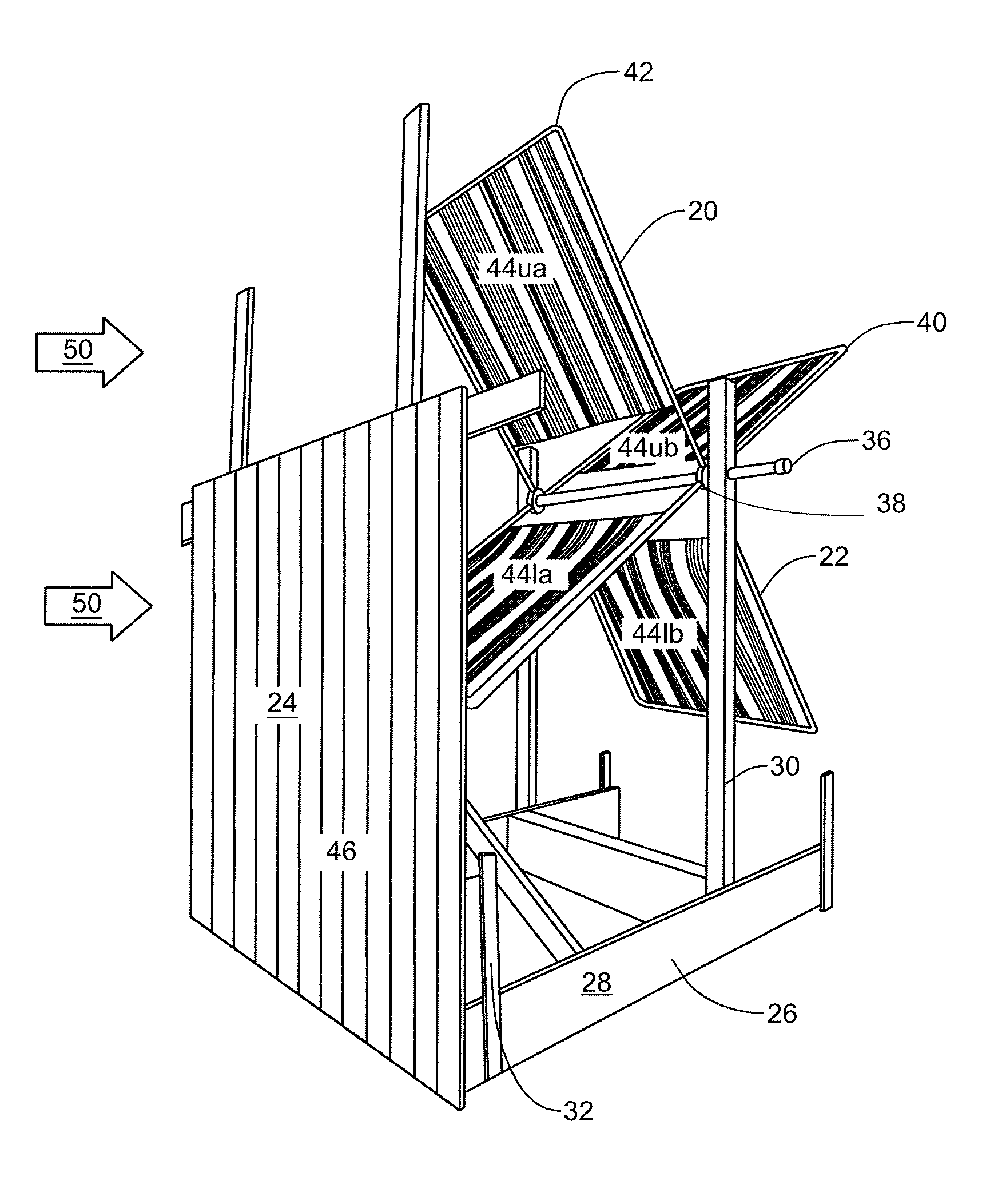
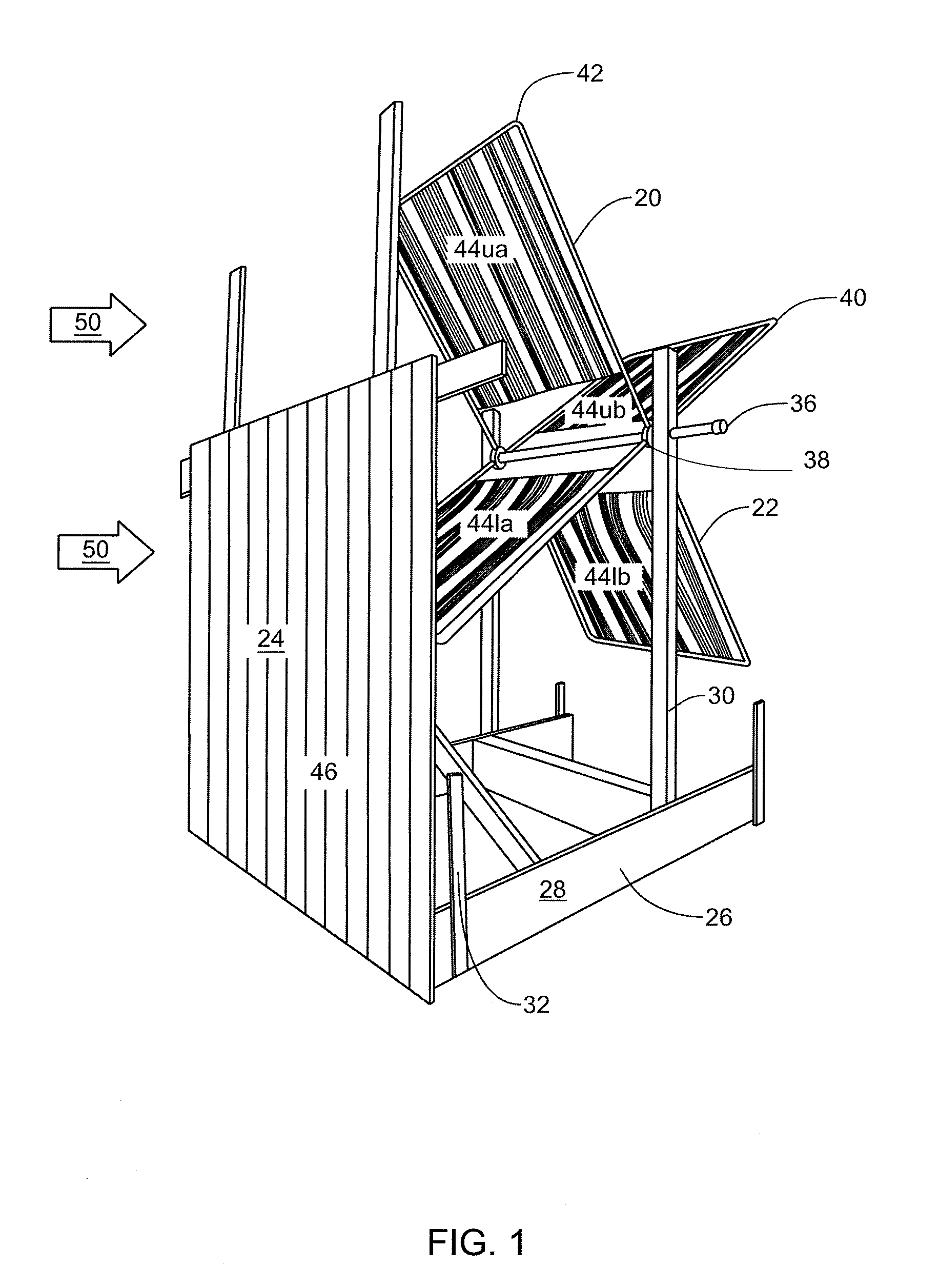
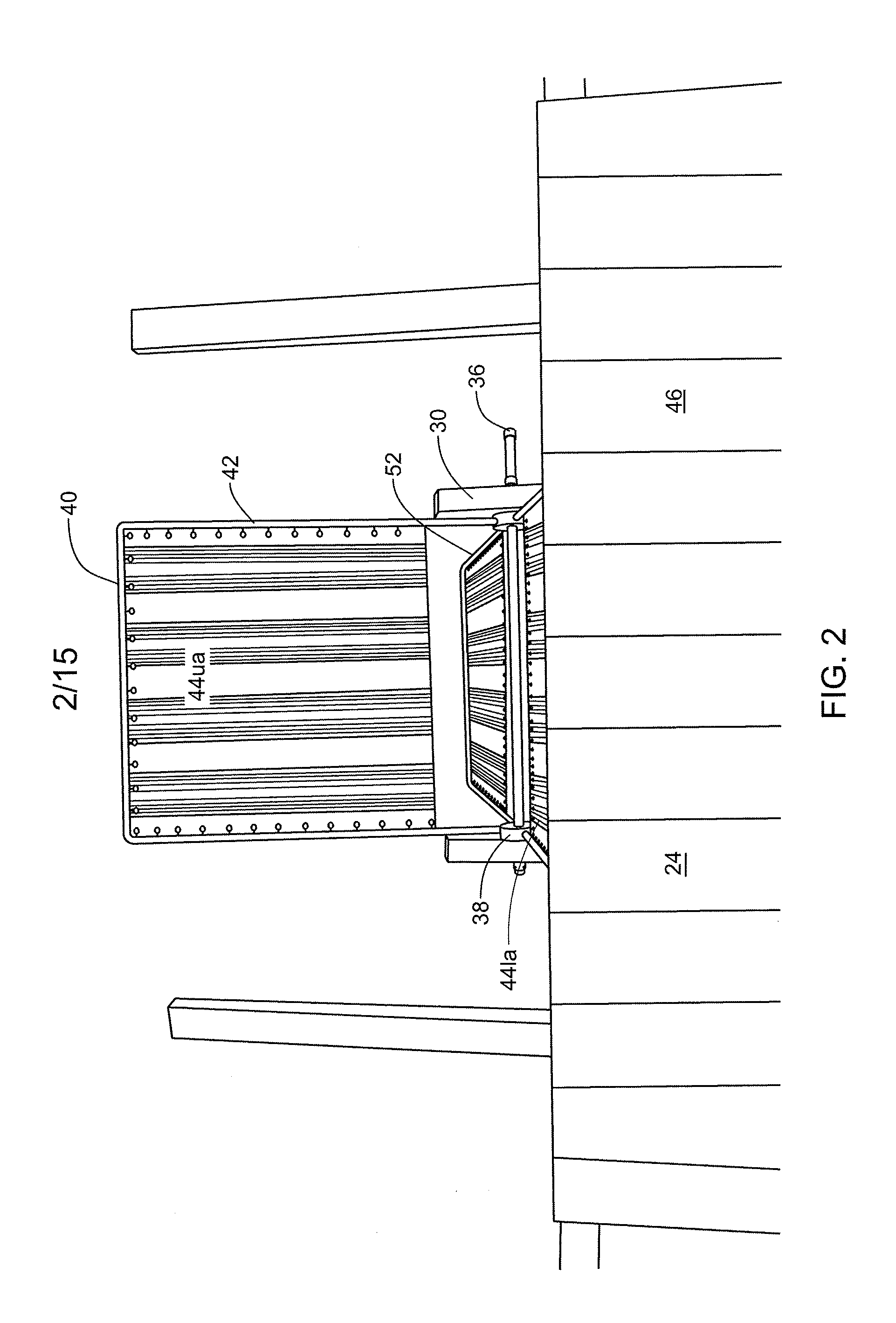
[0035]Referring to FIG. 1, a system 20 having a windmill device 22 and a wind guide system 24 is shown. The windmill device 22 has a mounting structure 26. In the embodiment shown, the mounting structure 26 is a ground structure 28 having an “H” shaped structure and a pair of vertical mounting poles 30. In addition, the mounting structu...


PUM


Abstract

A system and method of generating energy by transforming energy from a low-density substance, such as air flow or wind, into kinetic energy by directing the flow through a wind guide system towards panels that rotate in generally the same direction as the air flow. Furthermore, the system uses the ground and / or water as a surface for guiding the air flow towards the windmill devices. The wind guide system also limits air flow from engaging all the panels at the same.

Description

CROSS-REFERENCE TO RELATED APPLICATIONS[0001]The present application claims the benefit of Provisional Patent Application No. 61 / 195,513 filed Oct. 8, 2008, which is incorporated herein by reference.FIELD OF THE INVENTION[0002]The present invention is a system and method for producing energy from the action of wind. More particularly, it is a system and method for producing electricity through the action of wind on a wind wheel.BACKGROUND OF THE INVENTION[0003]There are numerous approaches to producing electricity from the movement of air or wind. Conventional systems place a series of large blades, blades generally over 30 feet, that rotate about a hub. The hub is positioned on the pole or tower and is located generally at least 80 feet above the ground or water. The blades generally rotate in a direction that is perpendicular to the flow of the air, i.e. wind. The system requires anchoring systems to secure the pole. In addition, it is generally desirous to have the blades even fu...

Claims


Application Information

Patent Timeline
IPC IPC(8): F03D9/00
CPCF03D3/002Y02E10/74F05B2240/40F03D3/0436Y02E10/728Y02E70/30F03D3/0454F03D9/12F03D9/25F03D9/48
Inventor BEANE, GLENN L.
Owner BEANE GLENN L
Learn More