Calibrated two port passive intermodulation (PIM) distance to fault analyzer

a passive intermodulation and fault analyzer technology, applied in the direction of transmission monitoring, receiver monitoring, instruments, etc., can solve the problems of unwanted additional signals, especially troubling, and achieve the effect of reducing the number of signals

Active Publication Date: 2010-04-08
ANRITSU CO
View PDF4 Cites 68 Cited by
  • Summary
  • Abstract
  • Description
  • Claims
  • Application Information

AI Technical Summary

Benefits of technology

[0011]To create a 2F1−F2 signal used for downconversion of the PIM source signal, in one embodiment a 2× frequency converter is connected to the signal source providing the signal of frequency F1. The signal source providing F2 for downconversion can be either the same as that provided to the PIM, or a separate signal source providing a frequency F2 minus the saw tooth offset sweep signal to allow a forward (ramp up) trace signal while eliminating a reverse (ramp down) trace generated with the saw tooth offset sweep.

Problems solved by technology

When these multiple signals are allowed to share the same signal path in a nonlinear transmission medium, unwanted additional signals occur.
This can be especially troubling when multiple connectors are involved as can be present in a PCS / AWS site tower.

Method used


Image

  • Calibrated two port passive intermodulation (PIM) distance to fault analyzer
  • Calibrated two port passive intermodulation (PIM) distance to fault analyzer
  • Calibrated two port passive intermodulation (PIM) distance to fault analyzer

Examples


Embodiment Construction

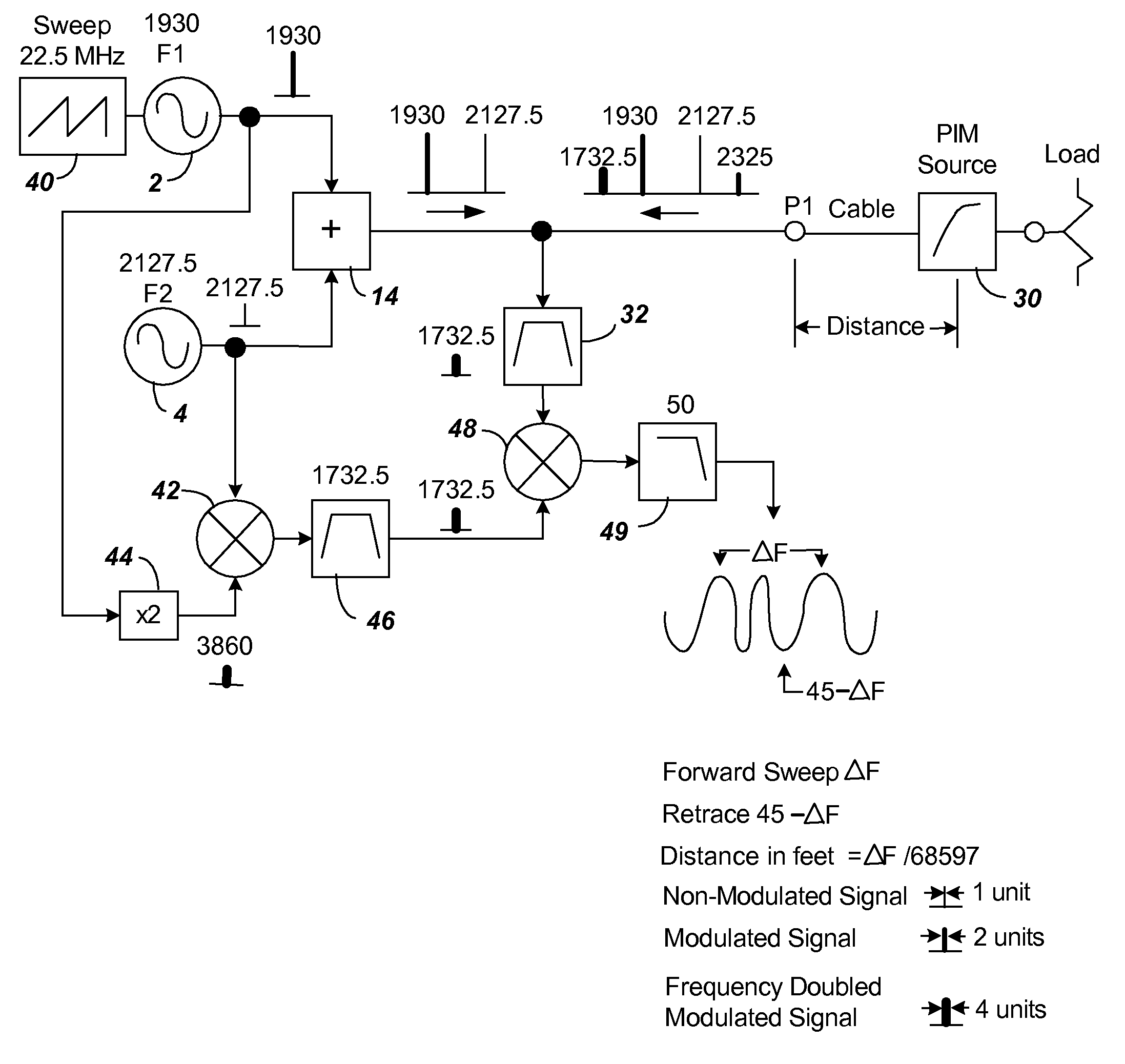
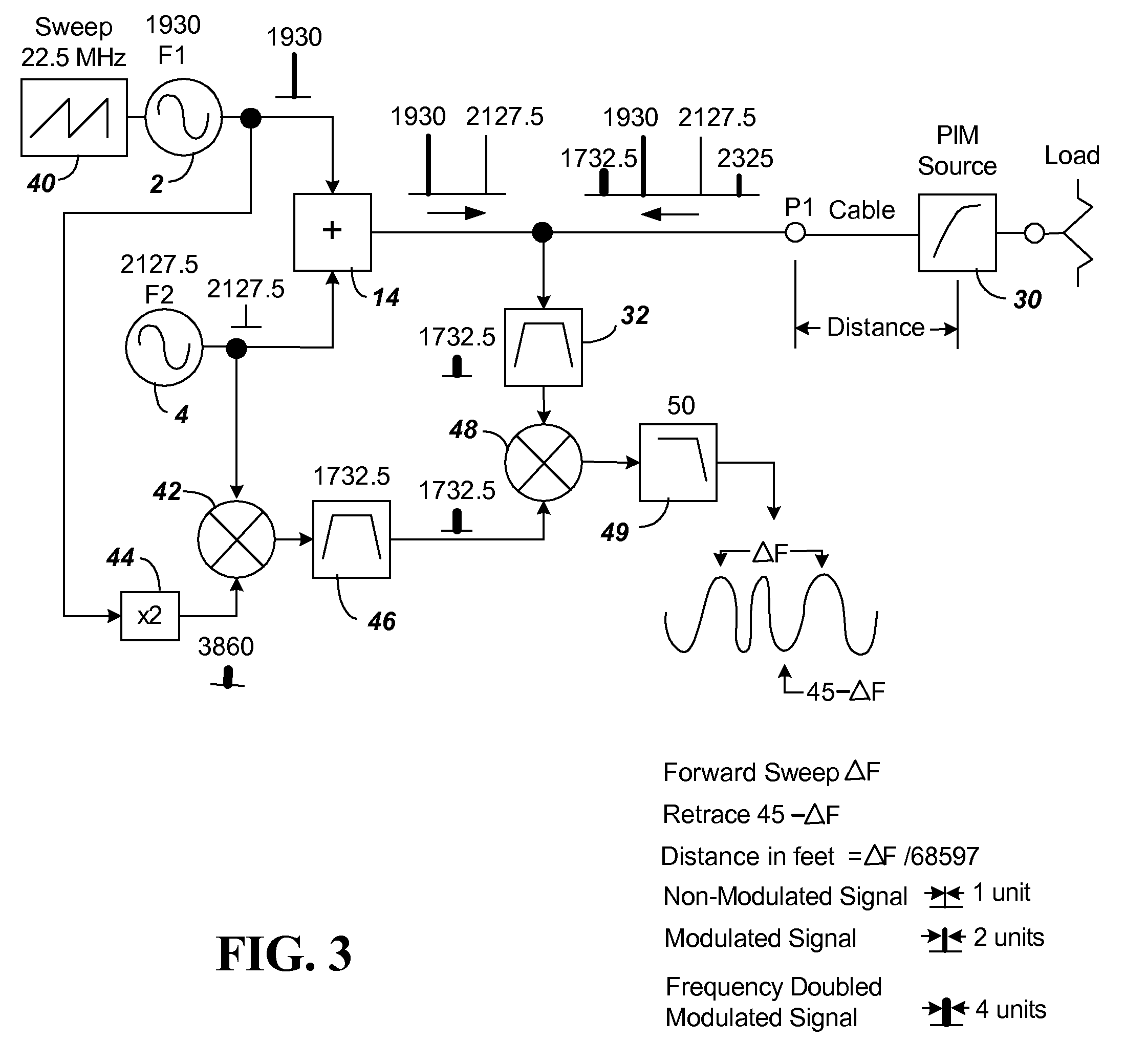
[0027]FIG. 3 shows the block diagram of components of a first embodiment of the present invention using FM-CW as a means of determining distance in a PIM measurement device. The FM sweep is introduced using sweep generator 40. The sweep generator 40 is connected to F1 source 2. For purpose of illustration, the sweep generator 40 is shown creating a 1.4844 uS period saw tooth causing a ±11.25 MHz modulation (ranging 22.5 MHz as shown) that is added to F1 of source 2. The FM sweep signal F1 and the fixed signal F2 when modified by the PIM source will produce the additional signals 2*(F1+FM)−F2 and 2*F2−(F1+FM). The delayed in time (distance) signal 2*(F1+FM)−F2 will be mixed with an internally generated non delayed in time (distance) signal 2*(F1+FM)−F2 to produce the desired measurement signal ΔF. The ΔF signal represents 68597× distance in feet. The distance to fault from P1 can, thus, be determined by distance in feet=ΔF / 68597

[0028]The circuitry of FIG. 3 has components added to ac...


PUM


Abstract

A PIM measurement circuit enables making forward and reverse PIM measurements on any 1 port (reflection) or 2 port (transmission) device with the ability to determine in distance where individual PIM impairments are located as well as their magnitude. The PIM measurement circuit includes two frequency sources that are provided through a combiner for a CW characterization of the PIM circuit. To enable distance determination, an FM measurement is created by using a saw tooth offset sweep generator attached to one of the two frequency sources. With downconversion and processing of signals from the PIM impairments, the FM signal provides a frequency variation that is converted using a Fourier transform or spectrum analysis for separation of frequencies, enabling determination of the distance of the PIM sources as well as their magnitudes.

Description

BACKGROUND[0001]1. Technical Field[0002]The present invention relates to a single (reflected) or a two port (transmission) distance to fault analyzer configured to measure passive intermodulation (PIM) created by two separate signal sources as well as to measure distance to a fault creating PIM.[0003]2. Related Art[0004]FIG. 1 shows a block diagram of components of a prior art test system setup for measuring PIM. The test system utilizes two signal sources 2 and 4, with a first signal source 2 producing a signal at frequency F1 and the second signal source 4 producing a signal at frequency F2. When these multiple signals are allowed to share the same signal path in a nonlinear transmission medium, unwanted additional signals occur. The 3rd order response is particularly troublesome as it produces signals at 2F1−F2 as well as 2F2−F1. The term widely uses for this phenomenon is Passive Intermodulation or PIM. The PIM test system of FIG. 1 measures this phenomenon.[0005]In the system o...

Claims


Application Information

Patent Timeline
Patent Type & Authority Applications(United States)
IPC IPC(8): G01R31/08
CPCH04B17/0085H04B17/27H04B17/103G01R31/11
Inventor BRADLEY, DONALD ANTHONYWITTY, ALAN CHARLES
Owner ANRITSU CO
Why Eureka
Try Eureka