Inkjet image-forming apparatus and method for printing
Active Publication Date: 2010-04-08
RISO KAGAKU CORP
View PDF2 Cites 8 Cited by
Summary
Abstract
Description
Claims
Application Information
AI Technical Summary
This helps you quickly interpret patents by identifying the three key elements:
Problems solved by technology
Method used
Benefits of technology
Benefits of technology
[0007]In order to start printing earlier under a low-temperature environment, conceivable way is to apply a larger driving voltage to the ink-ejection mechanism and thus to cause the ink-ejection mechanism to eject an appropriate amount of the ink. The application of a larger driving voltage, however, accelerates the ink-ejection speed, resulting in an increase in the mist production. Increased mist production in turn increases the mist attaching to the inside of the printer chassis. The mist flying about and the mist accumulated inside the printer chassisstain the printing sheet, and causes a problem of a lower-quality print.
[0008]An object of the invention, therefore, is providing an inkjet image-forming apparatus and a printing method which are capable of reducing both the mist production and the influence caused by the produced mist, starting a printing operation earlier under a low-temperature environment, and thereby completing the printing operation in a shorter time.
Problems solved by technology
The application of a larger driving voltage, however, accelerates the ink-ejection speed, resulting in an increase in the mist production.
The mist flying about and the mist accumulated inside the printer chassisstain the printing sheet, and causes a problem of a lower-quality print.
Method used
Image
Click on the blue label to locate the original text in one second.
Reading with bidirectional positioning of images and text.
Examples
embodiment 1
[0091]FIG. 5 is a flowchart illustrating a print-execution procedure according to the first embodiment of the invention. In the first embodiment, the printing execution under a low-temperature environment is controlled in terms of the print-interruption conditions that “a certain predetermined length of printing time has passed.”
[0092]Firstly, if the measured value of ink temperature is equal to or higher than the first reference temperature, e.g., 25° C., (S101: Yes), it is determined that the ink temperature is within the proper temperature range, and the printing processing for ordinary occasions (hereafter, simply referred to as the “ordinary printing processing”) is executed (S115). In this case, if the ink is being heated, the heating of ink is stopped (S114) before the execution of the printing processing. If the inks of different colors have different measured values of temperature from one another, the determination may be based, for example, on the average value of all the...
modified examples of embodiment 1
[0106]FIG. 9A is a chart illustrating the relationship among the “ink temperature,”“printing actions “heater actions,” and the “driving signals” in the print-execution procedure according to an modified example of the first embodiment of the invention. FIG. 9B is a chart corresponding to FIG. 9A and illustrating the relationship among the “ink temperature,”“printing actions,”“heater actions,” and the “driving signals” in a conventional print-execution procedure. The basic configurations of these charts are similar to those of FIGS. 7A and 7B, so that the description for the basic configurations of FIGS. 9A and 9B will not be given here. As FIG. 7A shows, the first embodiment is an example where the inkjet printer 100 interrupts the printing operation at the time t2, which is the predetermined time length Tm after the time t1. As FIG. 9A shows, the modified example of the first embodiment is an example where of the printing operation is completed at the time t2 which is earlier than ...
embodiment 2
[0108]FIG. 11 is a flowchart illustrating a print-execution procedure according to the second embodiment of the invention. In the second embodiment, the printing execution under a low-temperature environment is controlled in terms of the print-start conditions that “the number of sheets to be printed is equal to or smaller than a predetermined allowable number.”
[0109]Firstly, if the measured value of ink temperature is equal to or higher than the first reference temperature, e.g., 25° C., (S201: Yes), it is determined that the ink temperature is within the proper temperature range, and the ordinary printing processing is executed (S212). In this case, if the ink is being heated, the heating of ink is stopped (S211) before the execution of the printing processing. If the inks of different colors have different measured values of temperature from one another, the determination may be based, for example, on the average value of all the measured values of ink temperature, or on the lowe...
PUM
Abstract
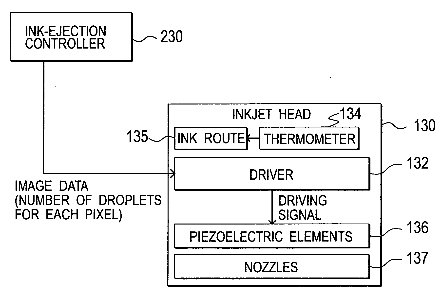
An image forming apparatus including: a print-job controller configured to receive a print job and control a printing operation based on the received print job; an ink-ejection driver configured to output a driving signal on the basis of the print job; an ink ejector configured to eject ink onto a paper sheet on the basis of the driving signal outputted by the ink-ejection driver; and an ink-temperature measuring unit configured to measure an ink temperature. When the ink temperature measured by the ink-temperature measuring unit is equal to or higher than a first reference temperature, the ink-ejection driver outputs a driving signal of a first voltage. When the ink temperature measured by the ink-temperature measuring unit is lower than the first reference temperature and is equal to or higher than a second reference temperature that is lower than the first reference temperature, the print-job controller performs the printing operation as long as predetermined conditions are satisfied for suppressing lowering of print quality possibly caused by ink ejection based on a driving signal of a second voltage that is higher than the first voltage and the ink-ejection driver outputs the driving signal of the second voltage while the printing operation is being performed.
Description
CROSS REFERENCE TO RELATED APPLICATION[0001]This application is based upon and claims the benefit of priority from the prior Japanese Patent Application Nos. 2008-262129 and 2008-262147, filed on Oct. 8, 2008, the entire contents of which are incorporated herein by reference.BACKGROUND OF THE INVENTION[0002]1. Field of the Invention[0003]The invention relates to an inkjet image-forming apparatus and a printing method, and specifically, to an image-forming apparatus and a printing method which are capable of reducing both the mist production and the influence caused by the produced mist as well as capable of reducing time to start a printing operation under a low-temperature environment.[0004]2. Description of the Related Art[0005]Inkjet printers, which have been widely used, form images by ejecting ink onto a printing sheet from printing heads. Printing heads in inkjet printers eject ink by applying a driving voltage to an ink-ejection mechanism such as a piezoelectric element. The ...
Claims
Application Information
Patent Timeline
Application Date:The date an application was filed.
Publication Date:The date a patent or application was officially published.
First Publication Date:The earliest publication date of a patent with the same application number.
Issue Date:Publication date of the patent grant document.
PCT Entry Date:The Entry date of PCT National Phase.
Estimated Expiry Date:The statutory expiry date of a patent right according to the Patent Law, and it is the longest term of protection that the patent right can achieve without the termination of the patent right due to other reasons(Term extension factor has been taken into account ).
Invalid Date:Actual expiry date is based on effective date or publication date of legal transaction data of invalid patent.

