Ink surface detecting systems and ink cartridge

a detection system and ink cartridge technology, applied in printing, other printing apparatuses, etc., can solve the problems of insufficient space for positioning the pair, inability to be positioned sufficiently close to each other, and reduce the flexibility of the design of the ink-jet printer

Inactive Publication Date: 2010-04-08
BROTHER KOGYO KK
View PDF6 Cites 4 Cited by
  • Summary
  • Abstract
  • Description
  • Claims
  • Application Information

AI Technical Summary

Benefits of technology

[0009]According to an embodiment of the present invention, an ink surface detecting system comprises an ink cartridge comprising an ink chamber configured to store ink therein and a pivoting member positioned in the ink chamber and configured to pivot in the ink chamber according to a position of a surface of the ink stored in the ink chamber. The pivoting member comprises a detected portion and a floating portion having a specific gravity less than a specific gravity of the ink stored in the ink chamber. The ink surface detecting system further comprises a mounting portion to which the ink cartridge is configured to be removably mounted. The ink surface detecting system further comprises a first optical detector positioned at the mounting portion, which comprises a first light-emitting portion configured to emit light in a direction intersecting a path along which the detected portion moves with respect to the ink chamber when the ink cartridge is mounted to the mounting portion and a first light-receiving portion configured to selectively assume two states according to a position of the detected portion in the path. The ink surface detecting system further comprises a second optical detector positioned at the mounting portion above the first optical detector, which comprises a second light-emitting portion configured to emit light in the direction intersecting the path when the ink cartridge is mounted to the mounting portion and a second light-receiving portion configured to selectively assume two states according to the position of the detected portion in the path. The pivoting member is configured to pivot with respect to the ink chamber in a first plane. The floating portion and the detected portion are positioned such that a second plane is positioned between the floating portion and the detected portion when the ink cartridge is mounted to the mounting portion, the second plane being perpendicular to the first plane, intersecting a center of a pivotal movement of the pivoting member, and being parallel to the direction of gravity. The floating portion comprises a first end positioned farthest from the center of the pivotal movement in the floating portion. The detected portion comprises a second end positioned farthest from the center of the pivotal movement in the detected portion. A first distance between the center of pivotal movement and the first end is different from a second distance between the center of pivotal movement and the second end.
[0010]According to another embodiment of the present invention, an ink surface detecting system comprises an ink tank comprising an ink chamber configured to store ink therein and a pivoting member positioned in the ink chamber and configured to pivot in the ink chamber according to a position of a surface of the ink stored in the ink chamber. The pivoting member comprises a detected portion and a floating portion having a specific gravity less than a specific gravity of the ink stored in the ink chamber. The ink surface detecting system further comprises a first optical detector comprising a first light-emitting portion configured to emit light in a direction intersecting a path along which the detected portion moves with respect to the ink chamber and a first light-receiving portion configured to selectively assume two states according to a position of the detected portion in the path. The ink surface detecting system further comprises a second optical detector positioned above the first optical detector, which comprises a second light-emitting portion configured to emit light in the direction intersecting the path and a second light-receiving portion configured to selectively assume two states according to the position of the detected portion in the path. The pivoting member is configured to pivot with respect to the ink chamber in a first plane. The floating portion and the detected portion are positioned such that a second plane is positioned between the floating portion and the detected portion when the ink cartridge is mounted to the mounting portion, the second plane being perpendicular to the first plane, intersecting a center of a pivotal movement of the pivoting member, and being parallel to the direction of gravity. The floating portion comprises a first end positioned farthest from the center of the pivotal movement in the floating portion. The detected portion comprises a second end positioned farthest from the center of the pivotal movement in the detected portion. A first distance between the center of pivotal movement and the first end is different from a second distance between the center of pivotal movement and the second end.
[0011]According to yet another embodiment of the present invention, an ink cartridge comprising an ink chamber configured to store ink therein and a pivoting member positioned in the ink chamber and configured to pivot in the ink chamber according to a position of a surface of the ink stored in the ink chamber. The pivoting member comprises a detected portion and a floating portion having a specific gravity less than a specific gravity of the ink stored in the ink chamber. The pivoting member is configured to pivot with respect to the ink chamber in a first plane. The floating portion and the detected portion are positioned such that a second plane is positioned between the floating portion and the detected portion. The second plane is perpendicular to the first plane, intersecting a center of a pivotal movement of the pivoting member. The floating portion comprises a first end positioned farthest from the center of the pivotal movement in the floating portion. The detected portion comprises a second end positioned farthest from the center of the pivotal movement in the detected portion. A first distance between the center of pivotal movement and the first end is greater than a second distance between the center of pivotal movement and the second end.
[0012]Other objects, features, and advantages of embodiments of the present invention will be apparent to persons of ordinary skill in the art from the following description of preferred embodiments with reference to the accompanying drawings.

Problems solved by technology

Nevertheless, depending on the structure of the ink jet printer, there might not be a sufficient space for positioning the pair of first light-emitting element and first light-receiving element and the pair of second light-emitting element and second light-receiving element which are apart from each other to a large extent.
Nevertheless, depending on the structure of the pair of first light-emitting element and first light-receiving element and the pair of second light-emitting element and second light-receiving element, the pair of first light-emitting element and first light-receiving element and the pair of second light-emitting element and second light-receiving element might not be able to be positioned sufficiently close to each other.
As such, the positions of the pair of first light-emitting element and first light-receiving element and the pair of second light-emitting element and second light-receiving element in the vertical direction depends on the positions of the ink surface which the ink amount detector means is made to detect, which reduces flexibility in design of the ink-jet printer.

Method used


Image

  • Ink surface detecting systems and ink cartridge
  • Ink surface detecting systems and ink cartridge
  • Ink surface detecting systems and ink cartridge

Examples


Embodiment Construction

[0058]Embodiments of the present invention and their features and technical advantages may be understood by referring to FIGS. 1-41, like numerals being used for like corresponding portions in the various drawings.

[0059]Referring now to FIG. 1 to FIG. 27, an ink discharging system according to a first embodiment of the present invention is described.

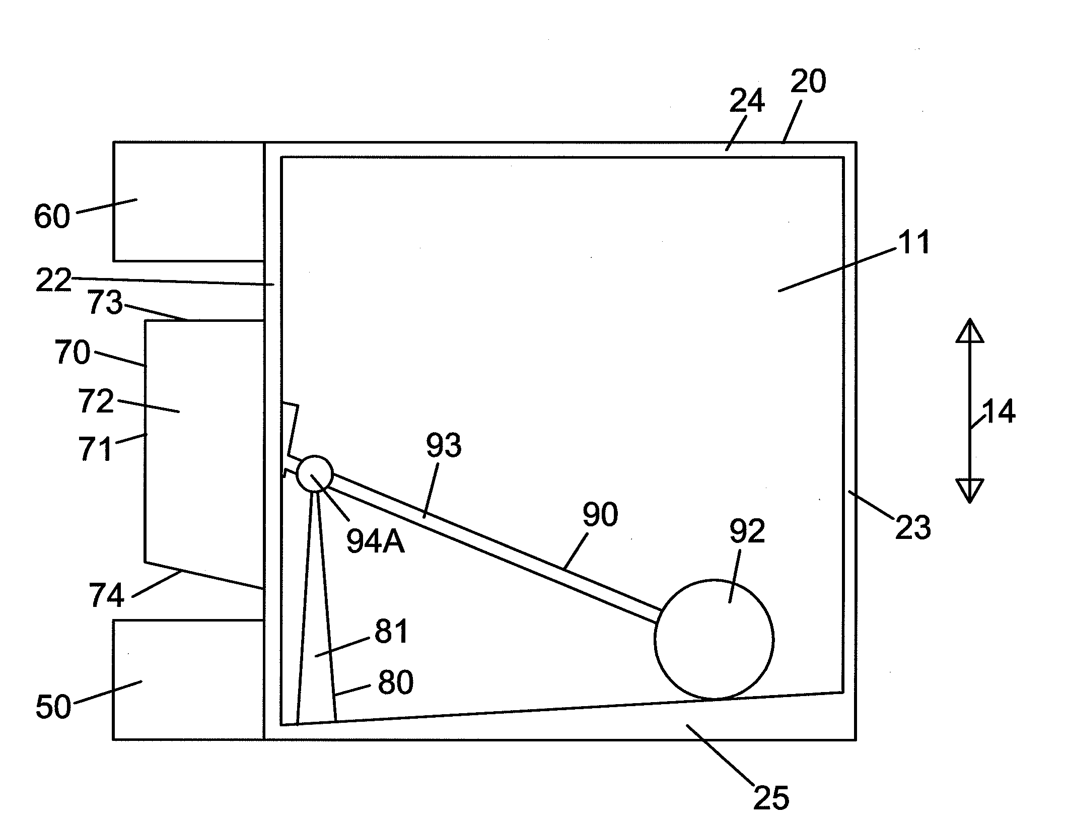
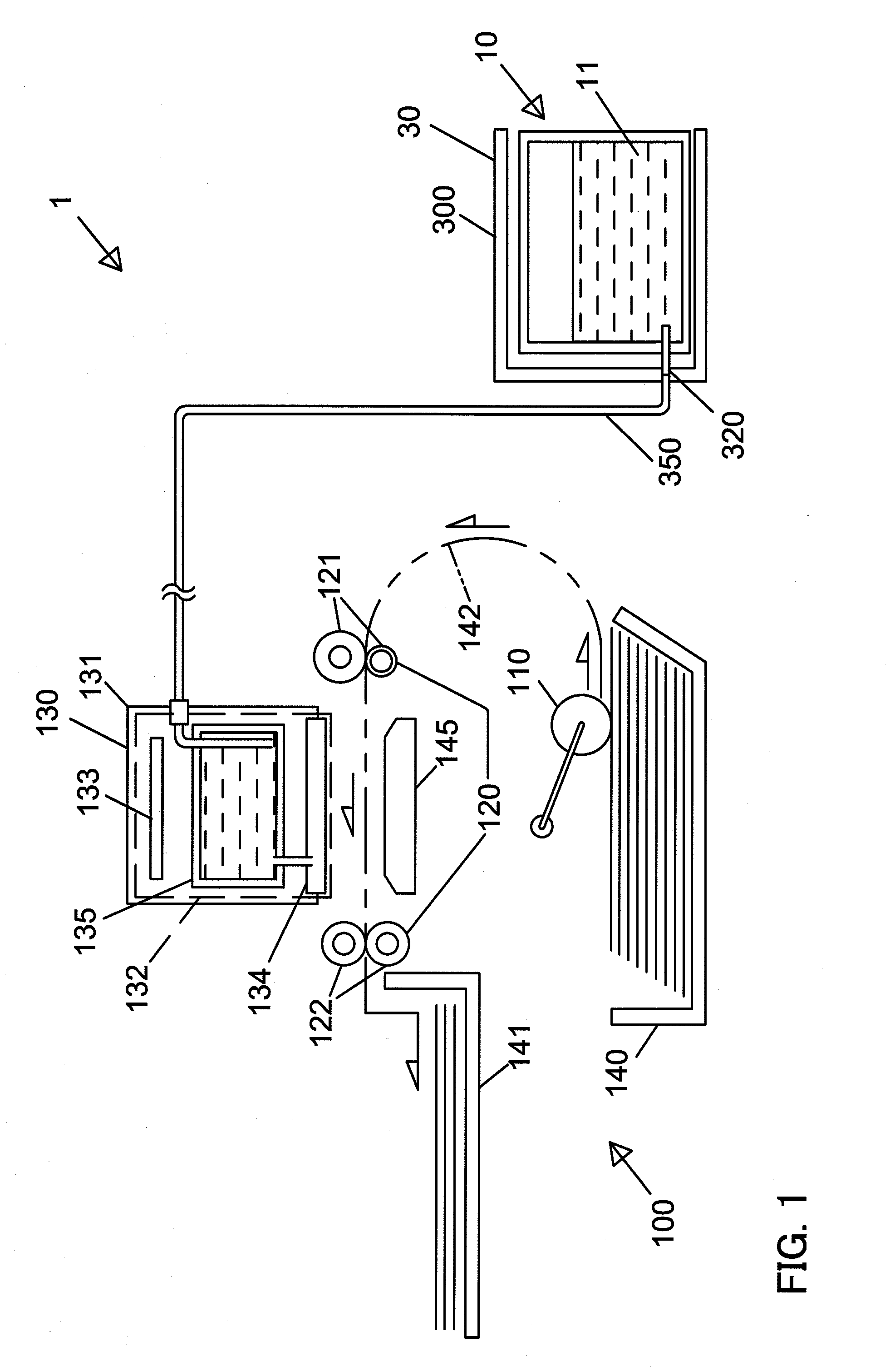
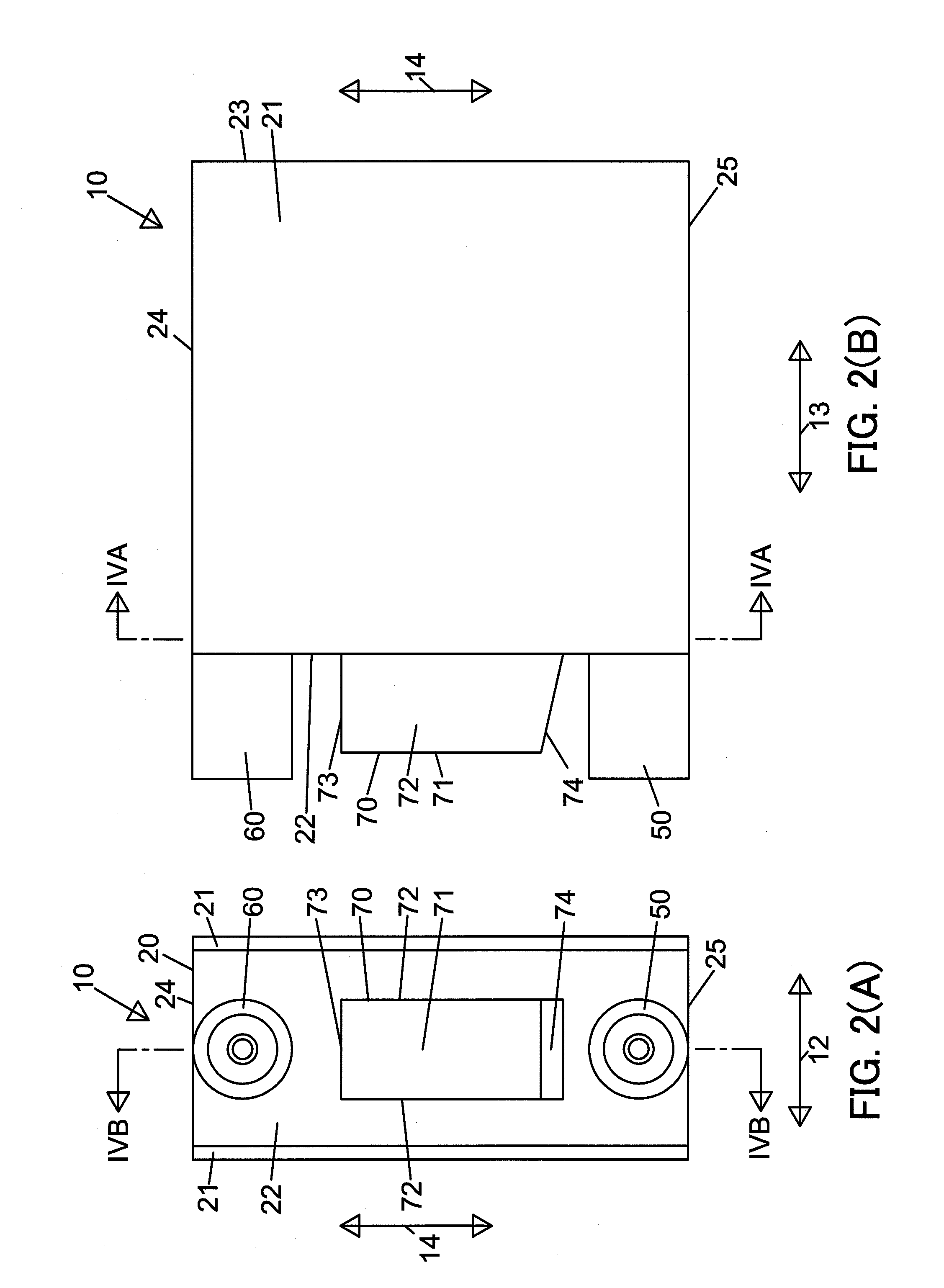
[0060] Referring to FIG. 1, an ink discharging system 1 as an example of the ink surface detecting system of the present invention comprises an ink-jet printer 100, and at least one ink cartridge 10 as an example of an ink tank and an ink cartridge of the present invention. The ink jet printer 100 is configured to print an image on a recording medium, for example, on a sheet of printing paper using ink in at least one color, for example, ink in four colors such as black ink, yellow ink, cyan ink, and magenta ink. The ink jet printer 100 comprises a paper feeding device 110, a transporting device 120, and a printing device 130. The ink je...


PUM


Abstract

An ink surface detecting system has an ink cartridge and a first optical detector, and a second optical detector positioned above the first optical detector. The ink cartridge has an ink chamber and a pivoting member having a detected portion and a floating portion. A first distance between the center of pivotal movement of the pivoting member and a first end of the pivoting member is different from a second distance between the center of pivotal movement and a second end of the pivoting member.

Description

CROSS-REFERENCE TO RELATED APPLICATION[0001]The present application claims priority from Japanese Patent Application No. JP-2008-260439, which was filed on Oct. 7, 2008, the disclosure of which is incorporated herein by reference in its entirety.BACKGROUND OF THE INVENTION[0002]1. Field of the Invention[0003]The present invention relates to an ink surface detecting system configured to conduct multistep detection of the position of ink surface in an ink chamber of an ink tank such as an ink cartridge, and to such an ink cartridge.[0004]2. Description of Related Art[0005]A known ink jet printer has a printhead, and ink is supplied from an ink tank to the printhead as ink is discharged from the printhead. The ink tank may be fixed to the ink-jet printer in some cases, or may be an ink cartridge configured to be removably mounted to the ink-jet printer in some cases. The ink jet printer can detect the amount of ink stored in the ink tank.[0006]An ink jet printer described in JP-A-8-132...

Claims


Application Information

Patent Timeline
Patent Type & Authority Applications(United States)
IPC IPC(8): B41J29/393
CPCB41J2/17513B41J2/1752B41J2/17566B41J2/17553B41J2/17523
Inventor NAKAMURA, HIROTAKE
Owner BROTHER KOGYO KK
Why Eureka
Try Eureka