
Magnetic field shield sheet for wireless power transmission and wireless power receiving module comprising same

a technology of wireless power transmission and magnetic field shielding sheet, which is applied in the direction of magnetic/electric field screening, shielding materials, transportation and packaging, etc., can solve the problems of reducing the required charging efficiency, and reducing the overall thickness, so as to secure the flexibility of the sheet itself, reduce the characteristic change, and reduce the overall thickness

Active Publication Date: 2018-11-01
AMOSENSE
View PDF0 Cites 4 Cited by
  • Summary
  • Abstract
  • Description
  • Claims
  • Application Information

AI Technical Summary

Benefits of technology

The present patent aims to improve the charging efficiency of wireless power transmission antennas while reducing their overall thickness. This is achieved by stacking additional sheets on one surface of a shielding sheet with a frame shape. The sheet outside the shielding sheet is made flexible by including fine pieces with at least one side of cured shape. This results in reduced characteristic changes, making the sheet more durable and reliable.

Problems solved by technology

When the thickness of the wireless power receiving module is designed to be 0.4 mm or less, or even 0.35 mm or less, it is difficult to realize the characteristics required for the wireless charging function.
Accordingly, since this stacking method has a limitation in reducing the overall thickness, a frame-type shielding sheet in which one sheet is inserted into the other is proposed.
However, it has been found that the required charging efficiency may not be satisfied in a severe condition where the total thickness of the wireless power receiving module is 0.4 mm or less.
However, the wireless power transmission antenna operable in a magnetic resonance method has a problem that the required charging efficiency is greatly reduced, for example, by 10% or more.

Method used


Image

  • Magnetic field shield sheet for wireless power transmission and wireless power receiving module comprising same
  • Magnetic field shield sheet for wireless power transmission and wireless power receiving module comprising same
  • Magnetic field shield sheet for wireless power transmission and wireless power receiving module comprising same

Examples


Embodiment Construction

[0033]Hereinafter, exemplary embodiments of the present disclosure will be described in detail with reference to the accompanying drawings, which will be readily apparent to those skilled in the art to which the present disclosure pertains. The present disclosure may be embodied in many different forms and is not limited to the embodiments described herein. In the drawings, parts not relating to the description are omitted for clarifying the present disclosure, and the same reference numerals are assigned to the same or similar components throughout the specification.

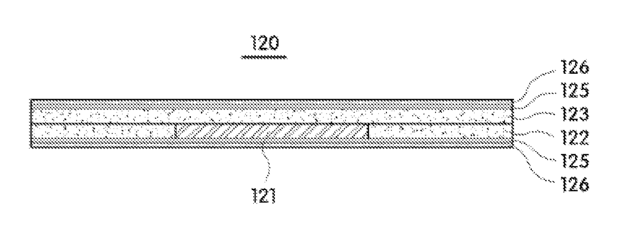
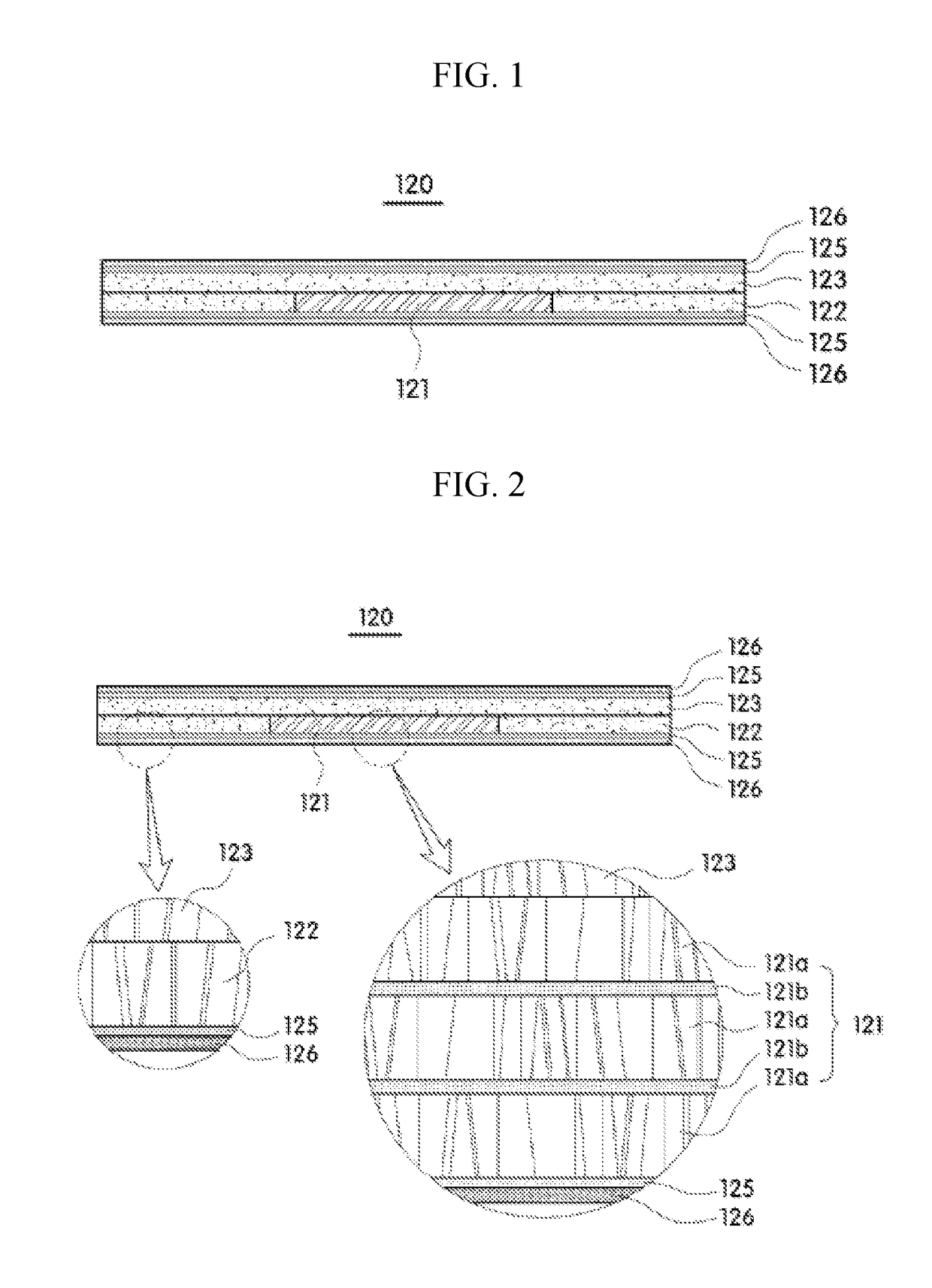
[0034]Referring to FIGS. 4 and 5, a wireless power receiving module 100 according to exemplary embodiments of the present disclosure may include an antenna unit 110 and a magnetic field shielding sheet 120.

[0035]The antenna unit 110 may be embedded in a portable electronic device such as a portable phone, a personal digital assistant (PDA), a portable multimedia player (PMP), a tablet, a multimedia device, and the like ...


PUM

PropertyMeasurementUnit
total thicknessaaaaaaaaaa

Abstract

There is provided a magnetic field shielding sheet for wireless power transmission. The present disclosure to provide a magnetic field shielding sheet for wireless power transmission that includes a first shielding sheet for shielding a magnetic field generated from a first wireless power transmission antenna operable in a magnetic induction method, a second shielding sheet for shielding a magnetic field generated from a second wireless power transmission antenna operable in a magnetic resonance method, and a third shielding sheet which is stacked on the same surface of the first shielding sheet and the second shielding sheet so as to cover the first shielding sheet and the second shielding sheet, for shielding the magnetic field generated from the second wireless power transmission antenna.

Description

CROSS-REFERENCE TO RELATED APPLICATION[0001]This U.S. non-provisional application claims priority under 35 USC § 119 from Korean Patent Application No. 10-2015-0152496, filed on Oct. 30, 2015 in the Korean Intellectual Property Office (KIPO), the disclosure of which is hereby incorporated by reference in its entirety.BACKGROUND1. Technical Field[0002]The present disclosure relates to a magnetic field shielding sheet for wireless power transmission and a wireless power receiving module including the same.2. Discussion of the Related Art[0003]Recently, various functions such as radio frequency identification (RFID), near field communication (NFC), wireless power transmission (WPT) and interactive pen tablet are added to portable terminals including mobile phones and tablet PCs.[0004]The portable terminal has a wireless charging function for wirelessly charging a built-in battery. The wireless charging can be performed by a wireless power receiving module built in the portable terminal...

Claims


Application Information

Patent Timeline
Patent Type & Authority Applications(United States)
IPC IPC(8): H01F10/20H02J7/02H05K9/00H02J50/12H02J50/70
CPCH01F10/20H02J7/025H05K9/0075H02J50/12H05K9/0007H02J50/70H05K9/0088H01F10/13
Inventor JANG, KIL JAE
Owner AMOSENSE
Learn More