Lens drive device

a technology of lens drive and drive shaft, which is applied in the direction of dynamo-electric components, dynamo-electric machines, instruments, etc., can solve the problems of high labor intensity, deformation of spring pieces, and low productivity, and achieve high degree of productivity and quality

Active Publication Date: 2012-01-31
SANKYO SEIKI MFG CO LTD
View PDF3 Cites 5 Cited by
  • Summary
  • Abstract
  • Description
  • Claims
  • Application Information

AI Technical Summary

Benefits of technology

[0006]In view of the problems described above, at least an embodiment of the present invention may advantageously provide a lens drive device which is capable of attaining a high degree of productivity and quality even when spring pieces are utilized as a power supply member to a coil.
[0008]In accordance with an embodiment of the present invention, portions of the coil ends of winding start and winding end of the coil which are wound around the binding pins are electrically connected with the spring pieces. Therefore, when the coil ends and the spring pieces are to be electrically connected with each other, the coil ends are not required to release from the binding pins. Further, preliminary solder for the coil end required to solder the coil end with the spring piece, reinforcing adhesion for preventing loosening of the coil end and the like are not required. In addition, problems are prevented in which, for example, solder slag is stuck to and around the spring piece and thus the spring piece is deformed and movement of the movable body is disturbed. Therefore, even when the spring piece is utilized in power supply to the coil, a high degree of productivity and quality can be attained.
[0010]In accordance with an embodiment of the present invention, the spring piece is provided with a coil connecting terminal part having a bent shape so as to be along a periphery of the binding pin, and the coil end is electrically connected with the coil connecting terminal part. Specifically, each of the two spring pieces is provided with a fixed side connecting part which is held by the support body, a movable side connecting part which is connected with the movable body, and an arm part which connects the movable side connecting part with the fixed side connecting part, and the movable side connecting part of the spring piece is provided with a coil connecting terminal part having a bent shape so as to be along a periphery of the binding pin. According to this structure, welding or soldering work is easily performed when the coil connecting terminal part and the coil end are to be connected with each other and, since the joining area becomes wider, a high degree of reliability can be obtained in the connected portion.
[0011]In accordance with an embodiment of the present invention, the coil connecting terminal part is provided with elasticity so as to be capable of being elastically deformed when the coil connecting terminal part is abutted with the portion of the coil end which is wound around the binding pin. According to this structure, since the coil connecting terminal part and the binding pin are disposed close to each other in an assembling step, a high degree of working efficiency is attained. In this case, it may be structured that the coil connecting terminal part is formed in a shape so that the coil connecting terminal part is capable of being resiliently bent toward an inner side in a radial direction, and a root portion of the coil connecting terminal part is formed with a cut-out part toward an inner side in the radial direction from an outer side so that the coil connecting terminal part is capable of being easily resiliently deformed.
[0012]In accordance with an embodiment of the present invention, the coil end is wound around the binding pin in plural turns and, among the plural turns, a part of the plural turns on a winding start side of the coil end of winding start which is wound around the binding pin and a part of the plural turns on a winding end side of the coil end of winding end which is wound around the binding pin are performed with soldering or melting operation for electrical connection with the spring piece, and remaining parts of the plural turns are not performed with soldering or melting operation. According to this structure, soldering or melting operation is not performed on a winding portion on a coil winding side of the coil end and thus flexibility of a coil wire can be secured. Therefore, even when a force is applied to the coil wire, the coil wire is hard to be disconnected.

Problems solved by technology

However, in order to connect the coil ends with the spring pieces by a method such as soldering as described in the above-mentioned Patent Reference, the coil ends are required to be bound around somewhere of the movable body until soldering is performed and, at the time of soldering, it is necessary to release the binding and thus much labors are required.
In addition, in order to perform soldering of the coil end to the spring piece, preliminary solder for the coil end, reinforcing adhesion for preventing loosening of the coil end and the like are required and thus its productivity is considerably low.
Therefore, quality problems may occur in which, for example, foreign matters such as solder slag are stuck to and around the spring piece and thus the spring piece is deformed and movement of the movable body is disturbed.

Method used


Image

  • Lens drive device
  • Lens drive device
  • Lens drive device

Examples


Embodiment Construction

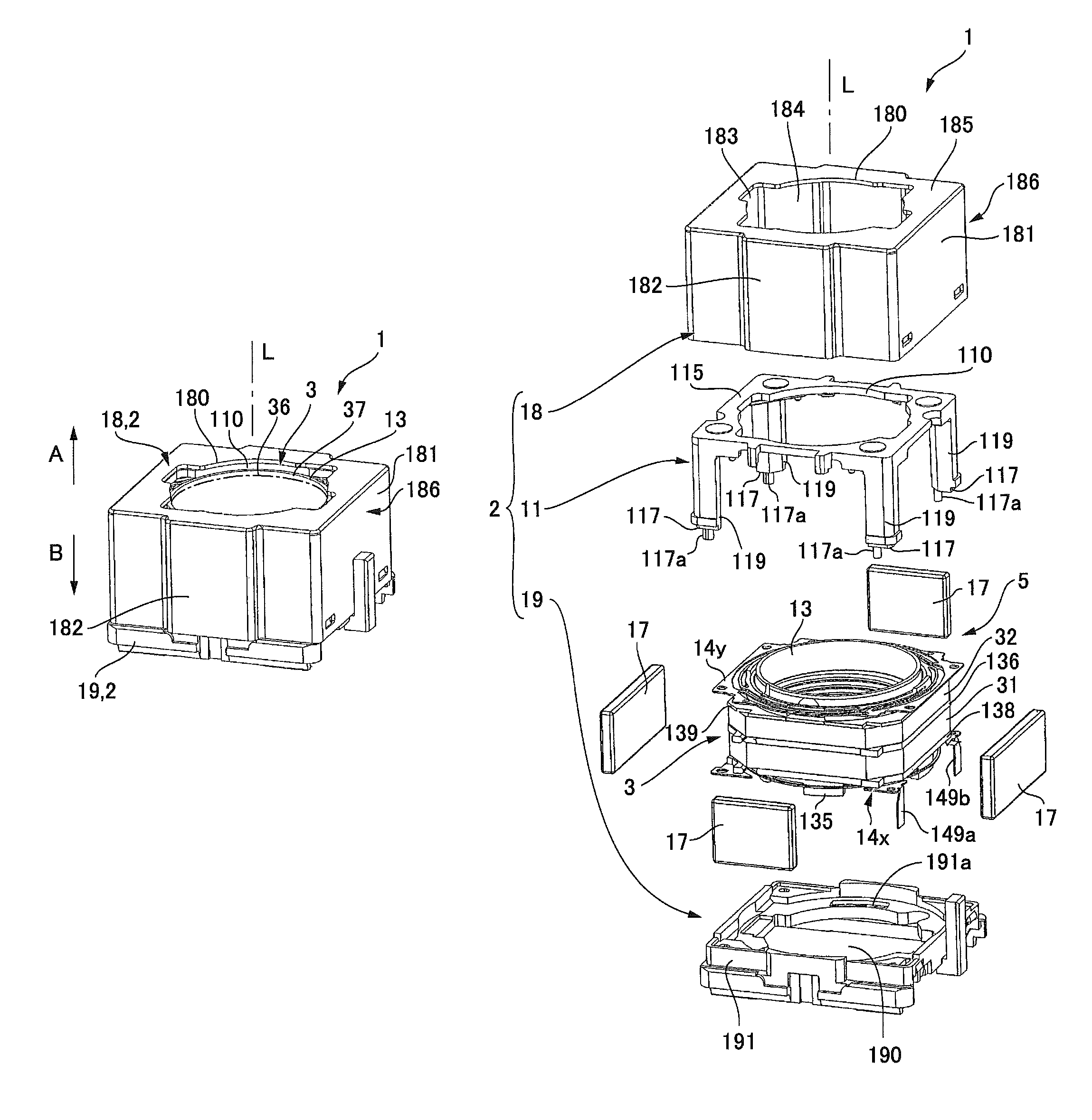
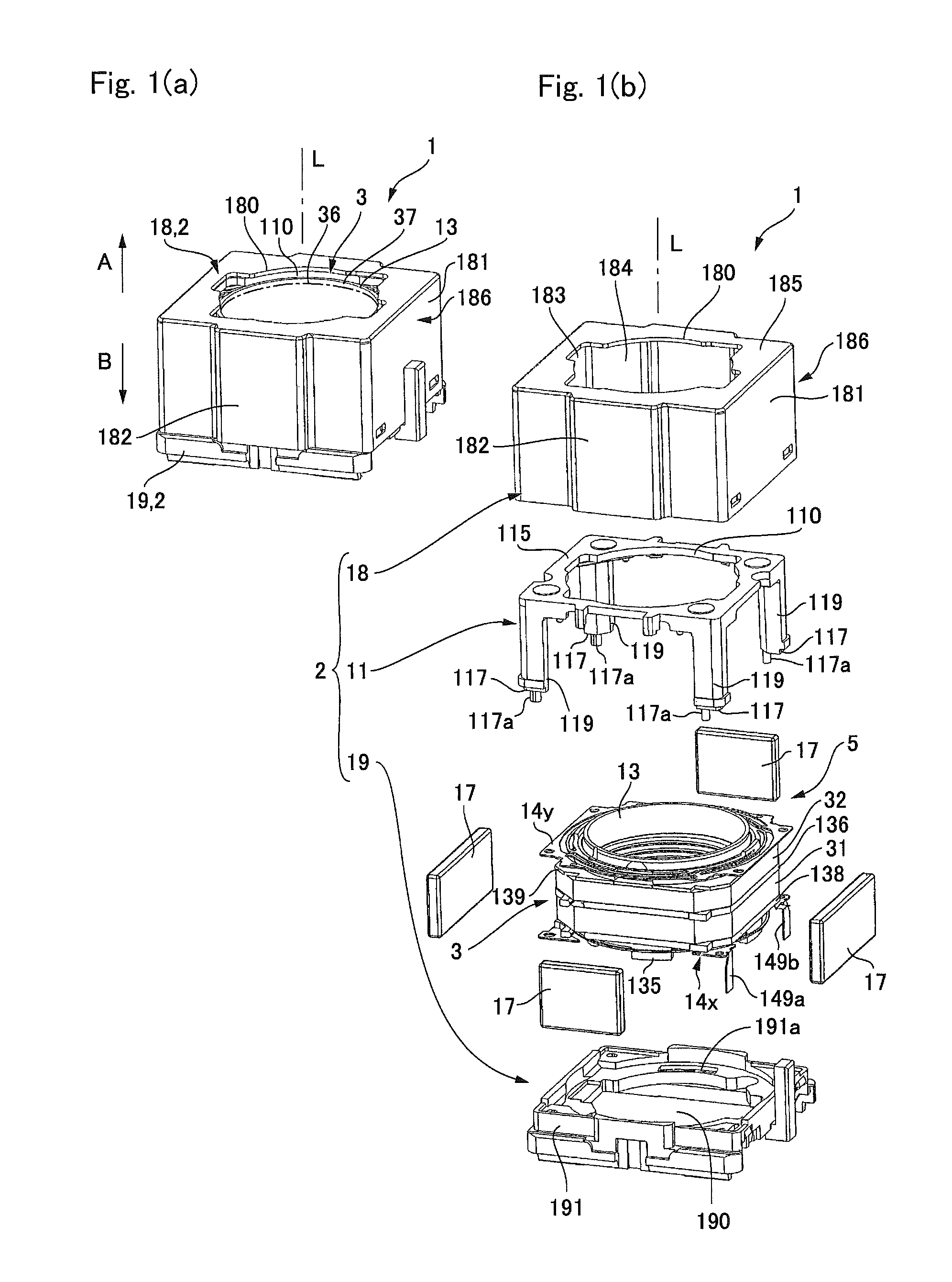
[0025]An embodiment of the present invention will be described below with reference to the accompanying drawings. A lens drive device which will be described below is capable of being mounted on various electronic apparatuses in addition to a cell phone with a camera. For example, the lens drive device may be mounted on a thin-type digital camera, a PHS, a PDA, a bar code reader, a monitoring camera, a camera for rear confirmation in a car, a door having optical authentication function or the like.

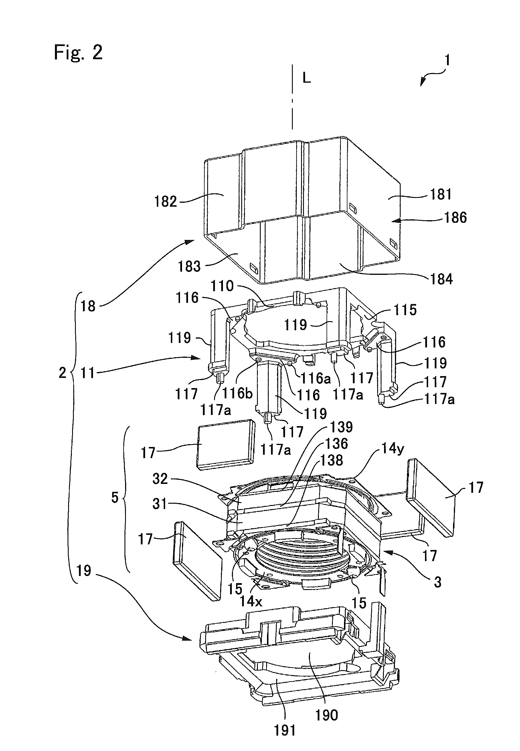
[0026]FIGS. 1(a) and 1(b) are explanatory perspective views showing the entire structure of a lens drive device in accordance with an embodiment of the present invention. FIG. 1(a) is an outward appearance view showing the lens drive device in accordance with an embodiment of the present invention which is viewed from an object to be photographed side and FIG. 1(b) is an exploded perspective view showing the lens drive device which is viewed from an object to be photographed side. FIG. 2 i...


PUM


Abstract

A lens drive device may include a support body, a movable body having a lens, a magnetic drive mechanism having a coil mounted on the movable body and a magnet mounted on the support body for magnetically driving the movable body in a lens optical axis direction, two spring pieces which are connected between the movable body and the support body for supporting the movable body and which is used as a power supply member to the coil, and two binding pins which are provided in the movable body and around which coil ends of winding start and winding end of the coil are wound. Portions of the coil ends which are wound around the binding pins are electrically connected with the spring pieces.

Description

CROSS REFERENCE TO RELATED APPLICATION[0001]The present invention claims priority under 35 U.S.C. §119 to Japanese Application No. 2009-138133 filed Jun. 9, 2009, the entire content of which is incorporated herein by reference.FIELD OF THE INVENTION[0002]At least an embodiment may relate to a lens drive device in which a power to a coil provided on a movable body having a lens is supplied through a spring member.BACKGROUND[0003]A lens drive device which is mounted on a cell phone with a camera, a digital camera or the like includes a movable body provided with a lens, a support body disposed on an outer side of the movable body, and a magnetic drive mechanism which magnetically drives the movable body in a lens optical axis direction. Further, the lens drive device is provided with a first spring member, which is connected with a base used as the support body and the movable body, and a second spring member which is connected with a cover used as the support body and the movable bod...

Claims


Application Information

Patent Timeline
Patent Type & Authority Patents(United States)
IPC IPC(8): G02B7/02
CPCG02B7/08G02B7/102H02K41/0356
Inventor TAKEI, HIROMITSUNAGAYOSHI, TATSUYA
Owner SANKYO SEIKI MFG CO LTD
Why Eureka
Try Eureka