Automatic focusing apparatus

a technology of automatic focusing and focusing lens, which is applied in the direction of color television details, instruments, television systems, etc., can solve the problems of inability to accurately calculate the position of the focus lens corresponding to the peak value of the af evaluation value, the af precision cannot be accurately calculated, and the mechanical system cannot follow the motion of the focus motor, so as to achieve accurate af control, reduce the control time, and reduce the effect of precision

Inactive Publication Date: 2010-04-08
CANON KK
View PDF11 Cites 17 Cited by
  • Summary
  • Abstract
  • Description
  • Claims
  • Application Information

AI Technical Summary

Benefits of technology

[0009]According to the present invention, an AF control time can be decreased since the acceleration / deceleration drive of the focus motor is executed. Further, since the acceleration / deceleration drive is performed using a predetermined acceleration / deceleration function, the position of the focus lens at the time when the evaluation value is acquired can be preferably calculated. Thus, a precise AF control can be achieved. Moreover, when the acceleration / deceleration function used in the acceleration / deceleration method is changed according to a situation, it is possible to more effectively decrease the AF time without lowering the AF precision.

Problems solved by technology

However, when the focus motor for driving the focus lens starts to be moved from a standstill condition, there is a possibility that the mechanical system cannot follow the motion of the focus motor due to adverse effects of inertia force and frictional force if the driving velocity is abruptly raised up to a certain velocity or more.
Hence, the position of the focus lens is liable to be erroneously controlled.
Accordingly, it is likely that a position of the focus lens corresponding to a peak value of the AF evaluation value cannot be accurately calculated.
Further, also when the lens is brought to a standstill, the step-out phenomenon is similarly likely to occur if the maximum velocity is abruptly brought to a standstill.

Method used


Image

  • Automatic focusing apparatus
  • Automatic focusing apparatus
  • Automatic focusing apparatus

Examples


Embodiment Construction

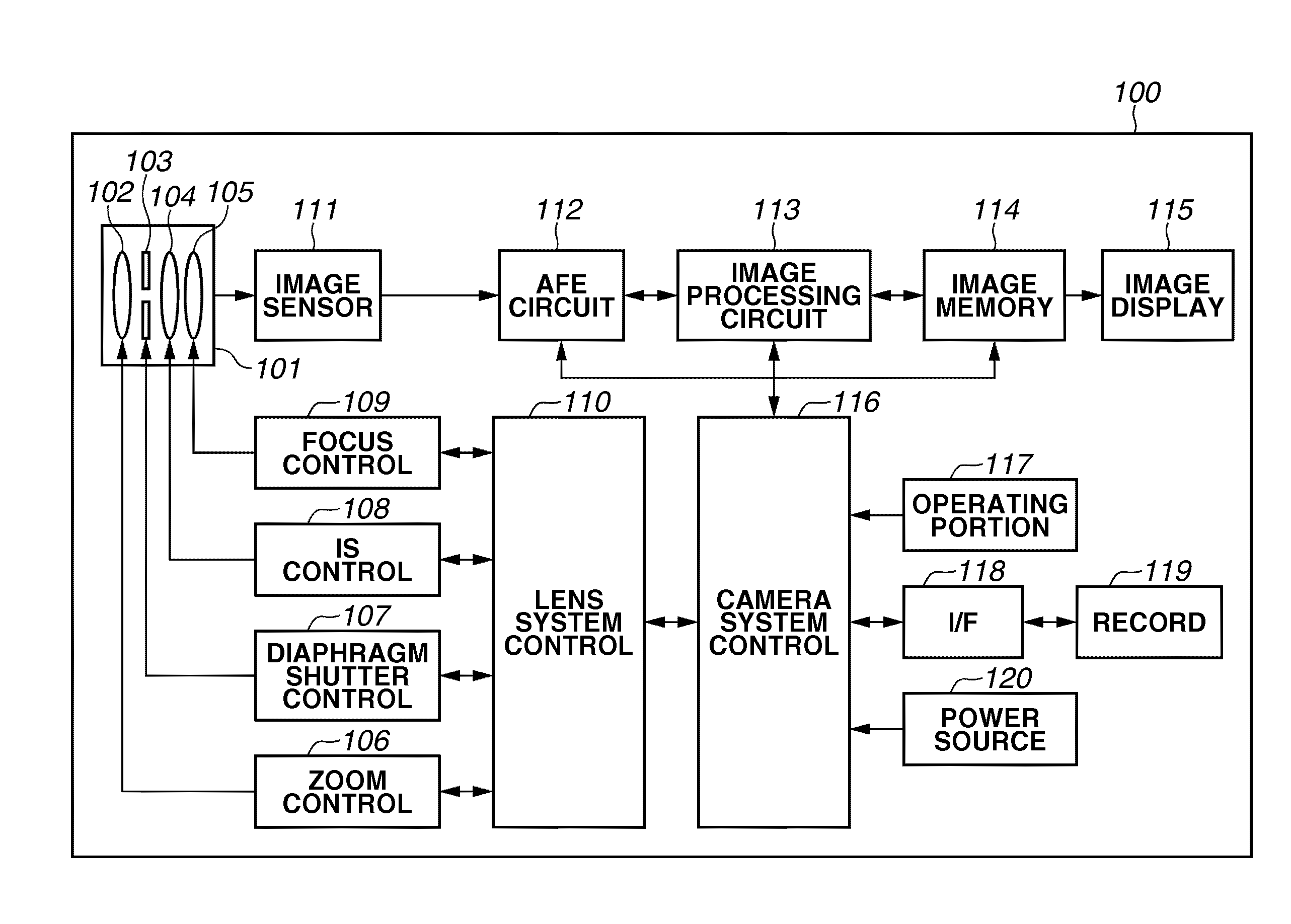
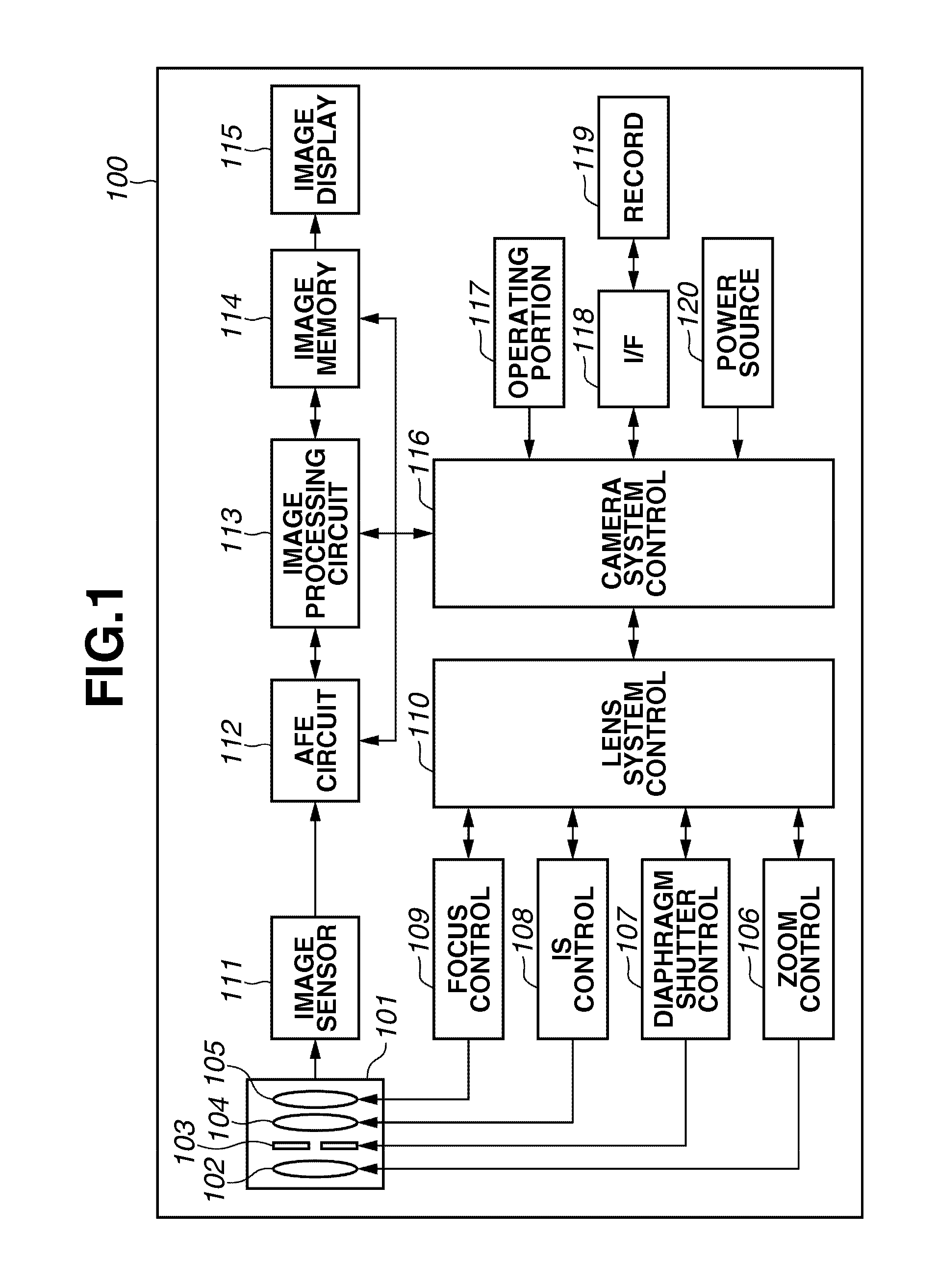
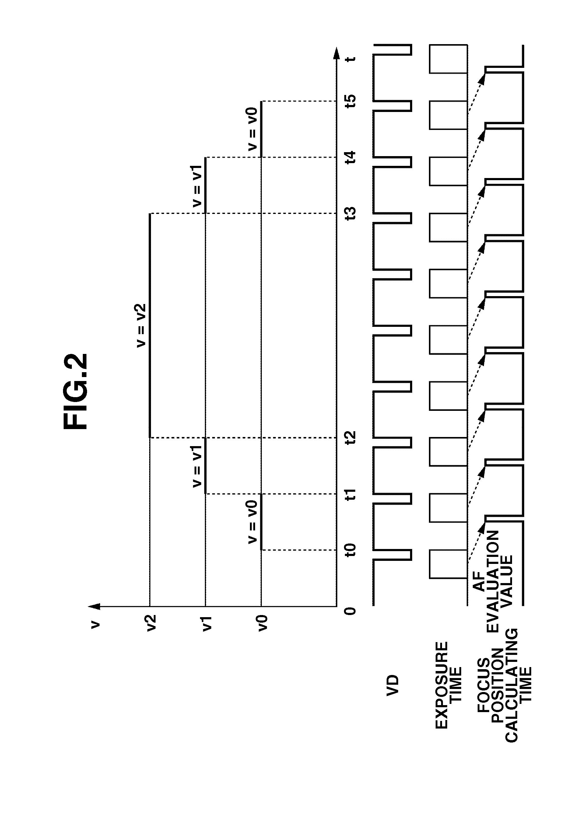
[0019]Embodiments of the present invention will hereinafter be described. An important point of the automatic focusing apparatus of the present invention is as follows. That is, a focus lens is driven by the acceleration / deceleration drive of the focus motor according to a predetermined acceleration / deceleration function. It is thereby possible to calculate the position of the focus lens during the AF control based on the acceleration / deceleration function. Accordingly, the position of the focus lens corresponding to an evaluation value acquired at any timing can be seized. Therefore, the focus position corresponding to a peak value of the AF evaluation value can be accurately detected. Based on this fundamental concept of the present invention, a fundamental embodiment of the automatic focusing apparatus according to the present invention has a construction described above in the summary of the invention. The above-described drive controlling portion can be achieved by a portion fo...


PUM


Abstract

An automatic focusing apparatus for performing focus adjustment of an object image includes an image pickup portion, an evaluating portion, a focus motor for driving a focus lens, and drive controlling portion. The image pickup portion converts an optical signal of an object image into an electric video signal. The evaluating portion calculates an evaluation value from the video signal obtained by the image pickup portion. The drive controlling portion controls an acceleration/deceleration drive of the focus motor according to a acceleration/deceleration function. The drive controlling portion accelerates the drive of the focus motor up to a target velocity, and decelerates the drive of the focus motor from the target velocity after the target velocity is reached, in synchronization with a synchronization signal for generating a timing of starting exposure for the optical signal of the image pickup portion.

Description

BACKGROUND OF THE INVENTION[0001]1. Field of the Invention[0002]The present invention relates to an automatic focusing apparatus usable in an image pickup apparatus such as a digital camera.[0003]2. Related Background Art[0004]Heretofore, in an automatic focusing (AF) apparatus, a contrast detecting method, in which a contrast of a video signal of an object image is detected to execute focusing operation, has been widely used. In the contrast detecting method, a phenomenon that the contrast of the video signal increase as a focus state approaches an in-focus condition is used. In other words, while a focus lens is moved, a position (focus position) of the focus lens corresponding to a peak of a contrast value (AF evaluation value) is detected. A solid state image sensing element, such as CCD and CMOS, is used as a device for converting an optical signal of the object image into an electric video signal, and the contrast value can be acquired by extracting a high frequency component ...

Claims


Application Information

Patent Timeline
Patent Type & Authority Applications(United States)
IPC IPC(8): H04N5/232
CPCH04N5/23212G03B13/36H04N23/673H04N23/633
Inventor TSUBUSAKI, AKIHIRO
Owner CANON KK
Why Eureka
Try Eureka