Optic system light guide with controlled output

a technology of optical system and output light, applied in the direction of lighting device details, lighting and heating apparatus, instruments, etc., can solve the problems of poor technology efficiency, current art devices, excessive energy consumption, etc., and achieve the effect of accurate control of the angle of output light, simple construction, and efficient transmission of ligh

Inactive Publication Date: 2010-04-08
RAMBUS DELAWARE
View PDF85 Cites 54 Cited by
  • Summary
  • Abstract
  • Description
  • Claims
  • Application Information

AI Technical Summary

Benefits of technology

[0014]An advantage of the optic system of the present invention is that it accurately controls the angles of the output light.
[0015]Another advantage of the optic system of the present invention is that it transmits light more efficiently than prior art devices.
[0016]Yet another advantage of optic system of the present invention is that it is simple in construction, and therefore easy and economical to manufacture.

Problems solved by technology

The chief shortcoming of current art devices is excessive energy consumption.
This is a result of the poor efficiency of the technology.
One drawback to prism films is that they have only limited control of the angles of the light output.
But a drawback to the Yamaguchi device is that it is extremely inefficient.
Even when the reflective surface is made with a high reflectance material, the losses in intensity are substantial.
Therefore while the control of light with this invention is superior to that of BEF devices, the efficiency is much poorer.
The range of control of these reflective structures is limited, and is not equivalent to the control afforded by devices such as Yamaguchi.
Further, the reflective structures are positioned very close to the LCD panel, which allows defects in their output to be easily seen by the viewer of the display.

Method used


Image

  • Optic system light guide with controlled output
  • Optic system light guide with controlled output
  • Optic system light guide with controlled output

Examples


Embodiment Construction

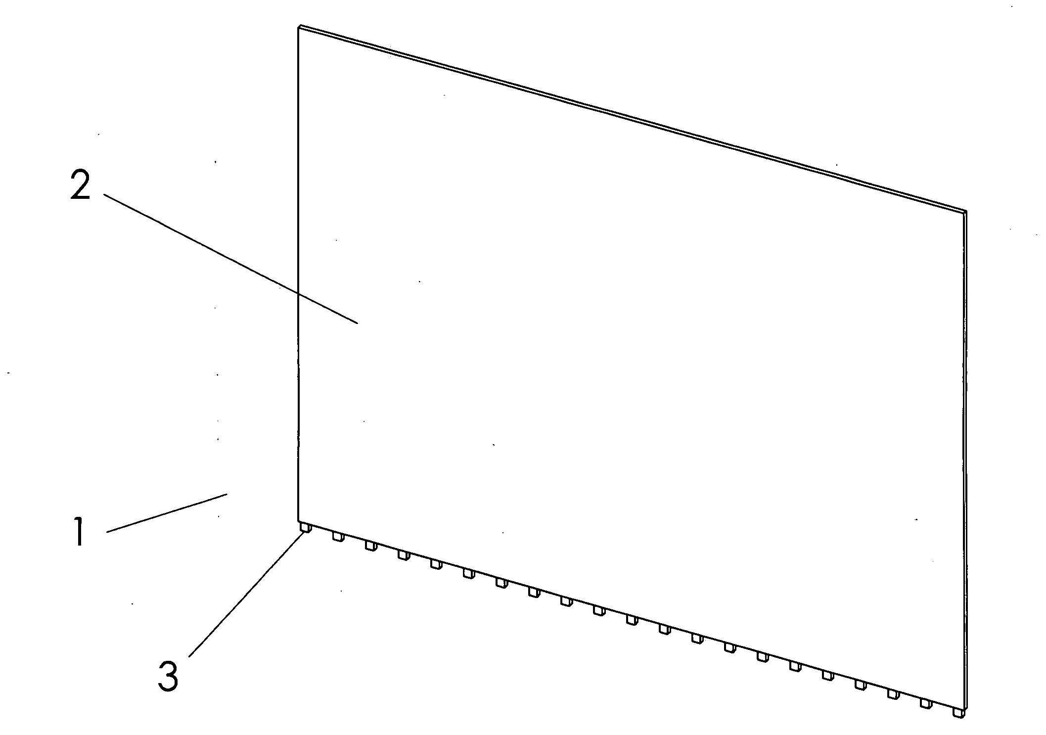
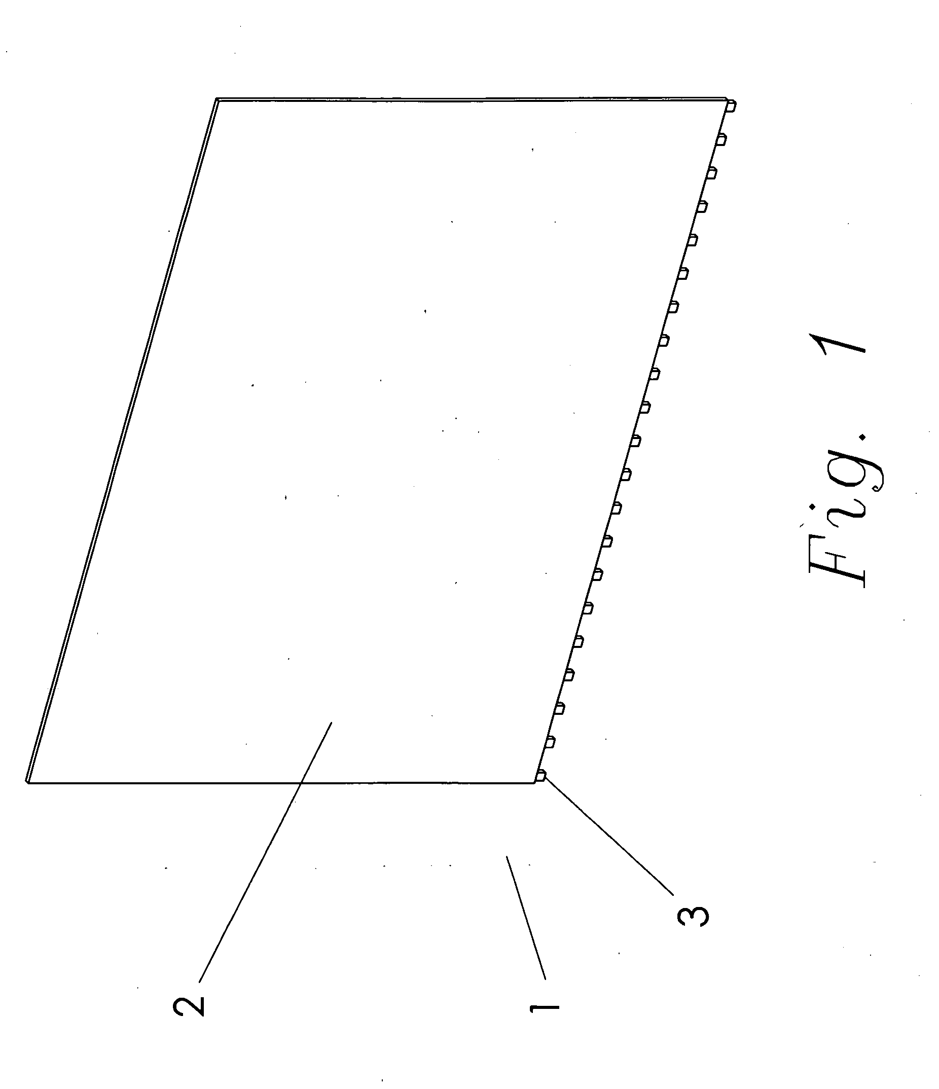
[0027]Referring first to FIG. 1, the light guide assembly 1 of the present invention comprises a light guide 2 with a planar surface and a plurality of LEDs 3. The LEDs 3 are located along a lower edge of the light guide 2. The number of colors of LEDs 3 and the side of the light guide 2 where the LEDs 3 are located would be a function of the size, shape and application of the light guide 2. The LEDs 3 can be situated on more than one side of the light guide 2. The LEDs 3 require electronics to drive them at the proper level. A person knowledgeable in LED driver electronics could devise many different circuits to accomplish this task. The preferred embodiment illustrated in FIG. 1 comprises a total of 27 LEDs 3 shown generally equally spaced along the bottom edge of the light guide 2. It should be recognized that other types of light sources such as incandescent or florescent, will suffice in the place of the LEDs 3.

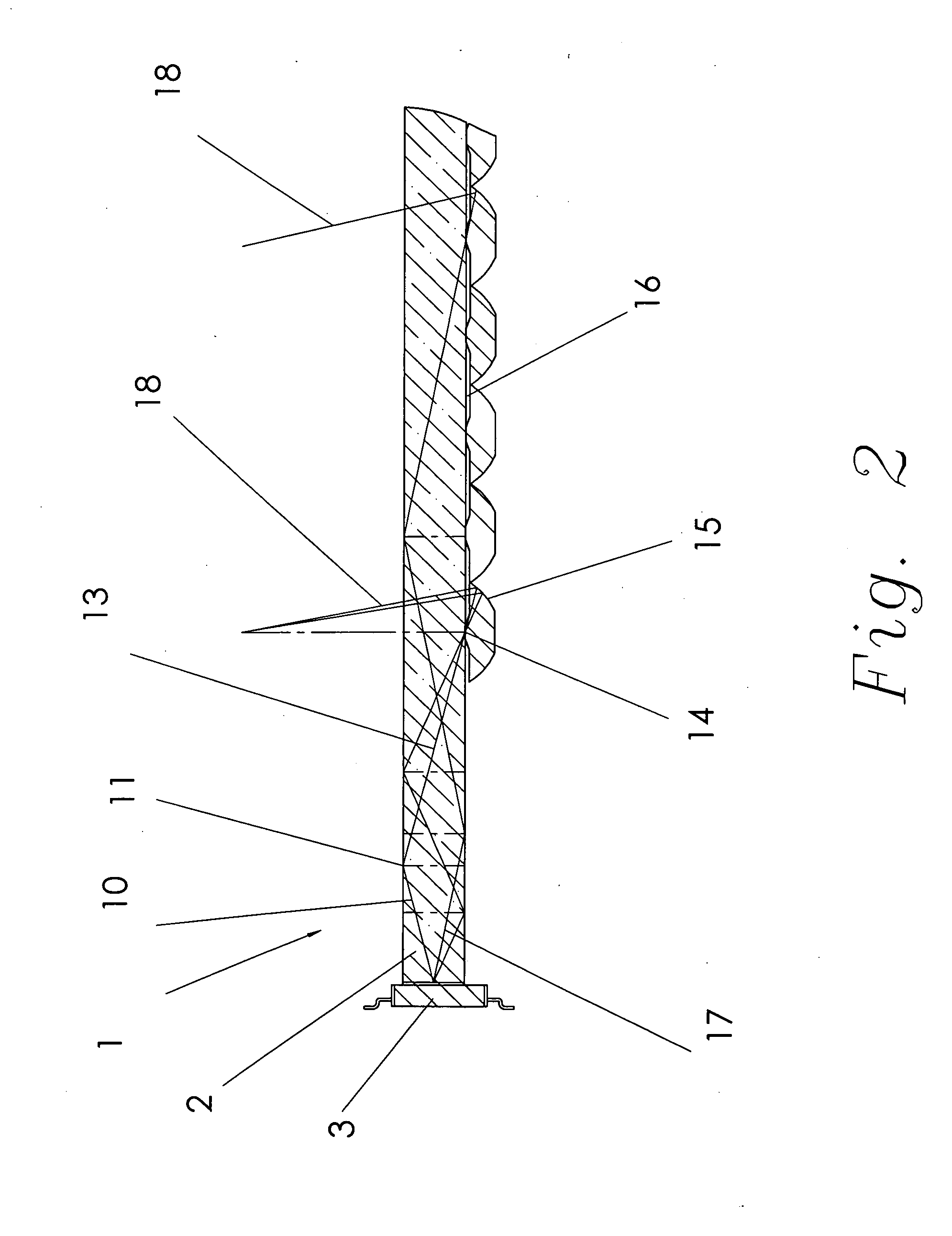
[0028]The light guide 2 is shown in a magnified side view in FIG. 2...


PUM


Abstract

A light guide with optics accurately controls the light exiting the guide. The device achieves accurate control of the reflected light by extracting light from a limited area of the light guide. The configuration of the reflectors used for the selective extraction determines the nature of the output light. The reflectors are preferably located on a side of the light guide opposite to an output side of the light guide.

Description

[0001]Applicant incorporates by reference herein his co-pending application “TIR Switched Flat Panel Display”, filed concurrently with this application.FIELD OF THE INVENTION[0002]This invention relates generally to light display devices, and more particularly is an optical system to control the direction light travels as it exits a light guide.BACKGROUND OF THE INVENTION[0003]Many products require an optical system to spread light over a large area and control the direction of the light as it exits the system. Recent improvements in the performance of LEDs, coupled with a concurrent reduction in the cost of production, have made LEDs a more viable option for many applications. However, many applications; such as LCD backlights, signs with backlights, overhead lighting, and automotive lighting; require the concentrated light that is generated by an LED to be spread over a large area, while still controlling the direction of the light. These applications require an improved optic sys...

Claims


Application Information

Patent Timeline
Patent Type & Authority Applications(United States)
IPC IPC(8): F21V7/04
CPCG02B6/0036G02B6/0038G02B6/0073G02B6/0068G02B6/0055
Inventor RICHARDSON, BRIAN EDWARD
Owner RAMBUS DELAWARE
Why Eureka
Try Eureka