
X-ray analysis instrument with adjustable aperture window

a technology of x-ray analysis and aperture window, which is applied in the direction of instruments, material analysis, and material analysis using wave/particle radiation, etc. it can solve the problems of inability to vary the surface curvature of a multi-layer x-ray mirror, limited beam conditioning possibilities, and complex mechanical structure, and achieves easy selection of a portion. , good control of beam geometry

Active Publication Date: 2010-04-08
INCOATEC
View PDF15 Cites 23 Cited by
  • Summary
  • Abstract
  • Description
  • Claims
  • Application Information

AI Technical Summary

Benefits of technology

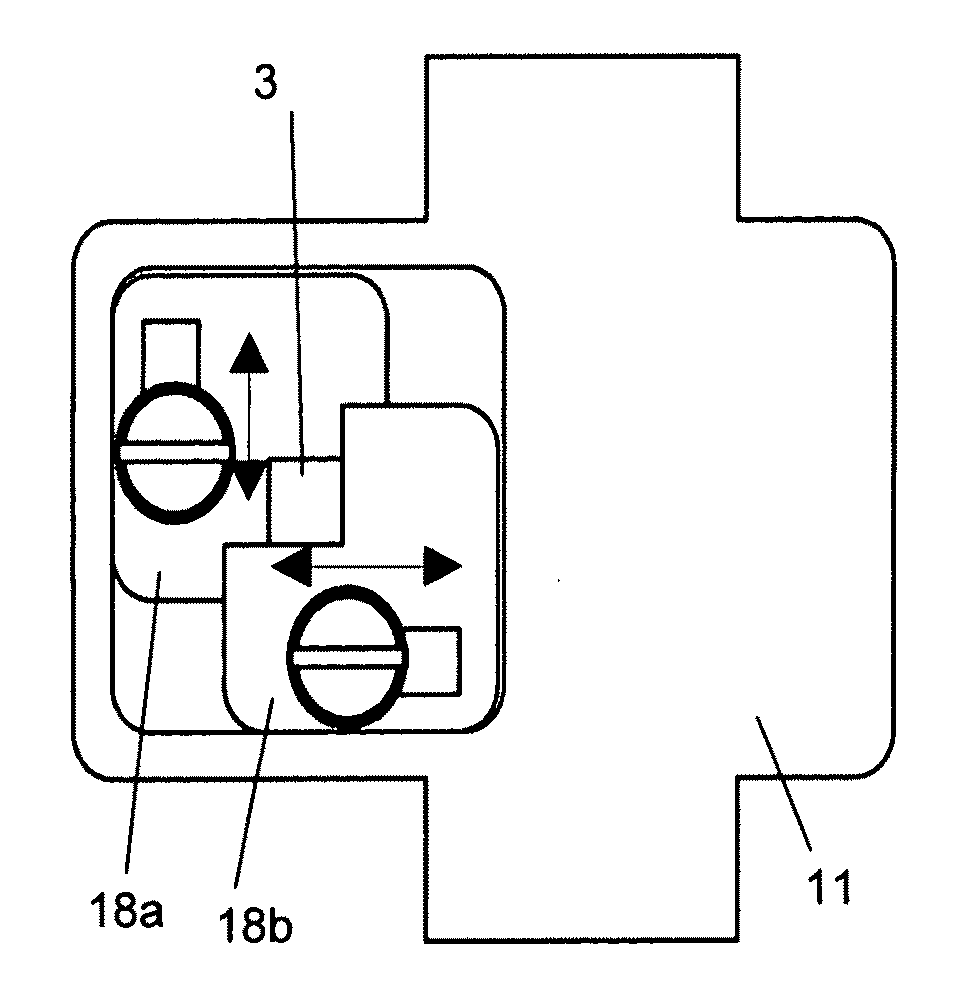
[0016]Due to the fact that the aperture window can be moved within a wide range, a partial area of the X-ray beam cross-section can be selected from two opposite sides. The X-ray beam generally has different properties in different regions of its cross-section such that the inventive collimator mechanism also facilitates selection of the properties of the transmitted X-ray beam portion. If the aperture opening is larger than the X-ray beam, VW>=AOE+RS preferably applies in the at least one direction, with VW: path of movement of the aperture window; AOE: extension of the aperture opening; RS: extension of the X-ray beam.
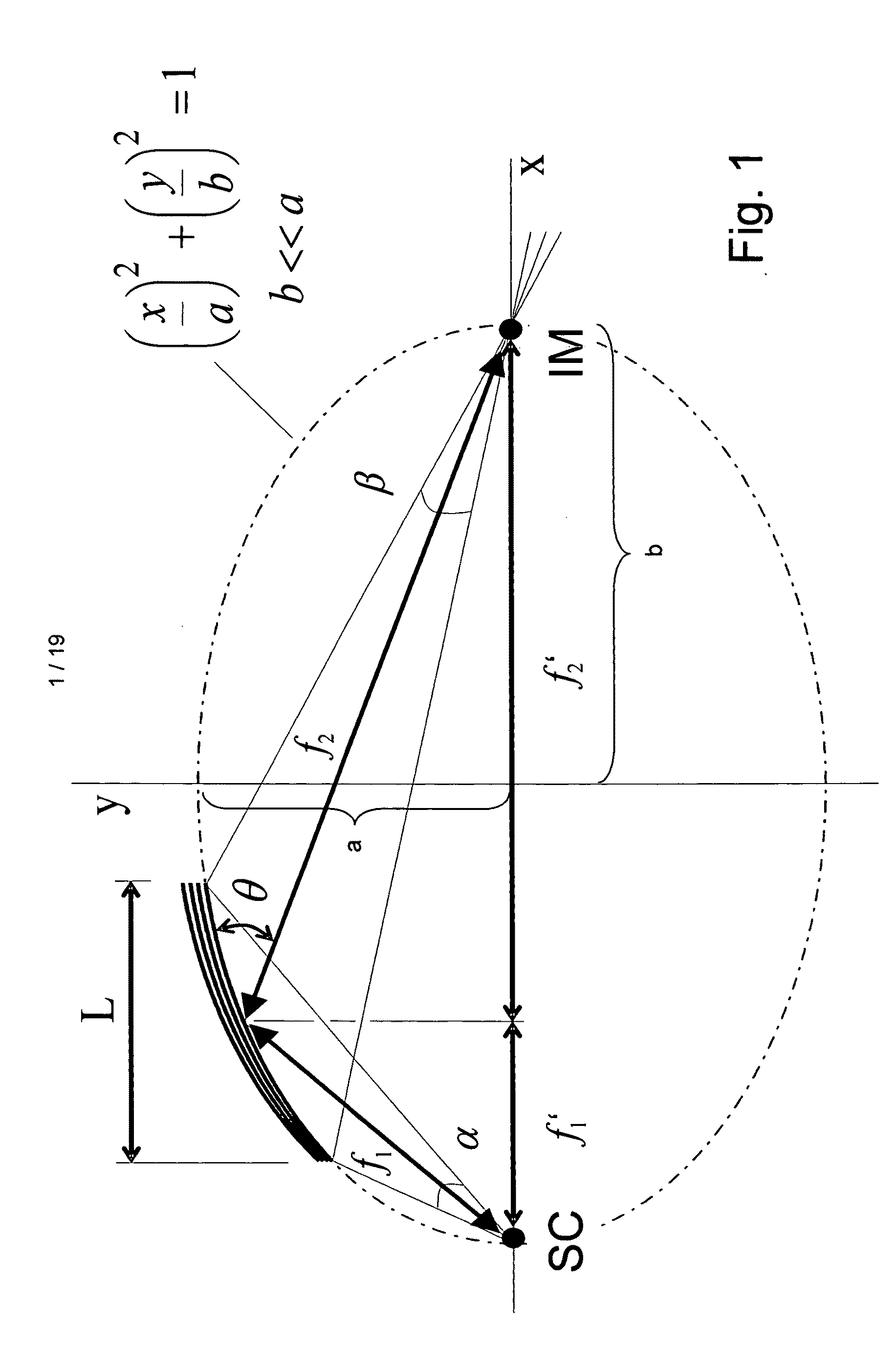
[0039]Finally, in a preferred variant of use, the aperture window is disposed in the X-ray beam between the X-ray optics and the sample. This, in turn, realizes good control of the beam geometry, in particular the beam convergence on the illuminated sample.

Problems solved by technology

In particular, it is not possible to vary the surface curvature of a multi-layer X-ray mirror or the layer separations in its multi-layers at a later time.
In both cases, the beam conditioning possibilities are limited.
Moreover, the mechanical structure is very complex.

Method used


Image

  • X-ray analysis instrument with adjustable aperture window
  • X-ray analysis instrument with adjustable aperture window
  • X-ray analysis instrument with adjustable aperture window

Examples


example of application

[0087]A crystal of a defined size and known lattice constants was mounted on an X-ray diffractometer (Smart Apex-II, Bruker AXS) at a fixed separation from the source and detector. The crystal had a long cell axis that showed a tendency for reflex superpositions with the selected detector separation. The crystal was oriented in such a fashion that the closely neighboring reflexes of the long cell axis on the detector were easily recognizable.

[0088]Several scans with completely opened aperture were performed and evaluated as a reference measurement. The overall flux of the source with opened aperture was measured with a photo diode and recorded. Then, the scans were repeated on the same crystal with the collimator being adjusted to half flux, and evaluated in the same fashion. The aperture was initially used to collimate out to half the flux in the direction of movement A (setting 1). The evaluation of the measured scans showed that the average normalized diffracted intensity was red...


PUM

PropertyMeasurementUnit
focus sizeaaaaaaaaaa
sizeaaaaaaaaaa

Abstract

An X-ray analysis instrument, in particular, an X-ray diffractometer (21), has an X-ray source (22; SC) that emits an X-ray beam (23), an X-ray optics (24), in particular a multi-layer X-ray mirror, and a collimator mechanism (BM), wherein the collimator mechanism (BM) forms an aperture window (2, 2′) with an aperture opening (3, 3′) through which at least part (26) of the X-ray beam (23) passes. The collimator mechanism (BM) comprises means for gradual movement of the aperture window (2, 2′) in at least one direction (A / B, x,y) transversely to the X-ray beam (23), the aperture opening (3, 3′) is at least as large as the cross-section (32) of the X-ray beam (23) at the location of the aperture window (2, 2′), and the path of movement (VWx, VWy) of the aperture window (2, 2′), which is accessible by the collimator mechanism (BM), in the at least one direction (A / B, x, y) is at least twice as large as the extension (RSx, RSy) of the X-ray beam (23) at the location of the aperture window (2, 2′) in this direction (A / B, x, y). The X-ray analysis instrument offers a wider scope of beam conditioning possibilities.

Description

[0001]This application claims Paris Convention priority of DE 10 2008 050 851.9 filed Oct. 8, 2008 and EP 09 000 179.3 filed Jan. 9, 2009 the complete disclosures of which are hereby incorporated by reference.BACKGROUND OF THE INVENTION[0002]The invention concerns an X-ray analysis instrument, in particular, an X-ray diffractometer, comprising[0003]an X-ray source that emits an X-ray beam,[0004]an X-ray optics, in particular, a multi-layer X-ray mirror,[0005]and a collimator mechanism, wherein the collimator mechanism forms an aperture window with an aperture opening through which at least part of the X-ray beam passes.[0006]An X-ray analysis instrument of this type is disclosed e.g. in DE 10 2004 052 350 A1.[0007]X-ray diffractometry is an efficient method for non-destructive chemical analysis of, in particular, crystalline samples. In modern X-ray diffractometers, the X-ray beam that is generated by an X-ray source is directed onto a sample via a multi-layer optics and the diffrac...

Claims


Application Information

Patent Timeline
Patent Type & Authority Applications(United States)
IPC IPC(8): G01N23/20
CPCG21K1/04
Inventor MICHAELSEN, CARSTENBELGARD, STEFANIEGRAF, JUERGEN
Owner INCOATEC
Learn More