Fuel cell assembly

a technology of fuel cell and assembly, which is applied in the direction of fuel cell details, fuel cells, electrochemical generators, etc., can solve the problems of increasing the complexity and cost of the operational unit, and adding considerably to the cost of each implementation, so as to reduce the overall height and width of the assembly, improve the air flow, and improve the effect of uniformity

Inactive Publication Date: 2010-04-08
HOOD PETER DAVID +1
View PDF3 Cites 21 Cited by
  • Summary
  • Abstract
  • Description
  • Claims
  • Application Information

AI Technical Summary

Benefits of technology

[0015]The enclosure may comprise an inlet air filter at a first end of the air flow path and an air exhaust at a second opposing end. This helps to reduce the overall height and width of the assembly. A reducing tapered section may be incorporated, extending from the inlet air filter to the first tapered air volume, to improve uniformity of air flow to the stack.
[0016]An increasing tapered section may also be provided extending from the second tapered air volume to the air exhaust, so as to improve air flow and reduce any pressure drop across the assembly.

Problems solved by technology

Designing such manifolds can lead to increased complexity and cost of the operational unit.
A further complication is the need to design a different fuel cell assembly for each different application, since each application will tend to have its own power requirements in terms of required voltages and currents as well as space.
Redesigning the assembly for each application can add considerably to the cost of each implementation.

Method used


Image

  • Fuel cell assembly
  • Fuel cell assembly
  • Fuel cell assembly

Examples


Embodiment Construction

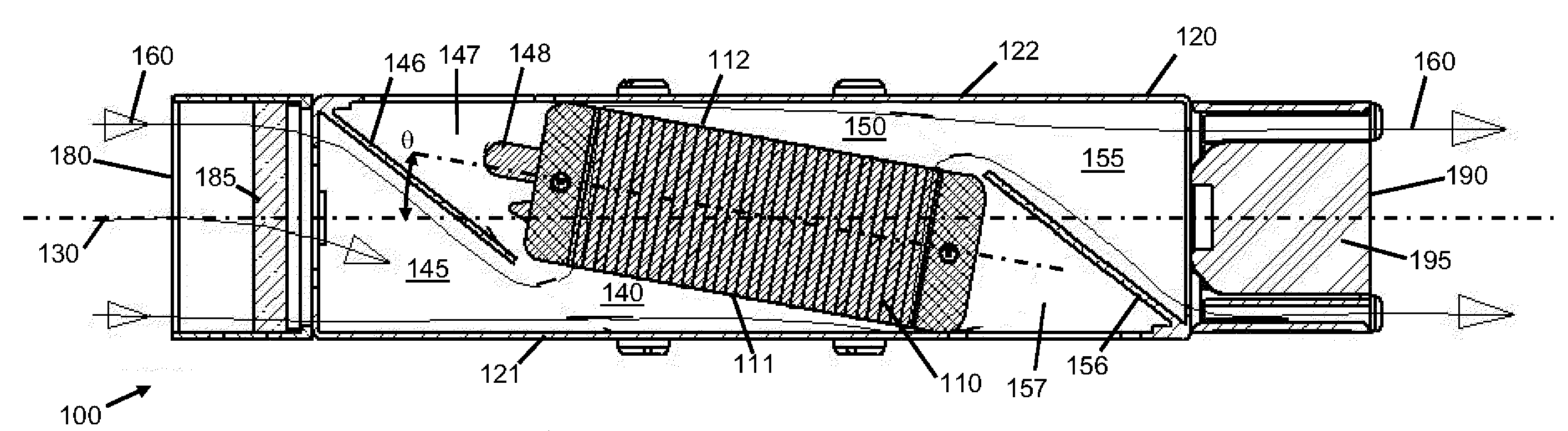
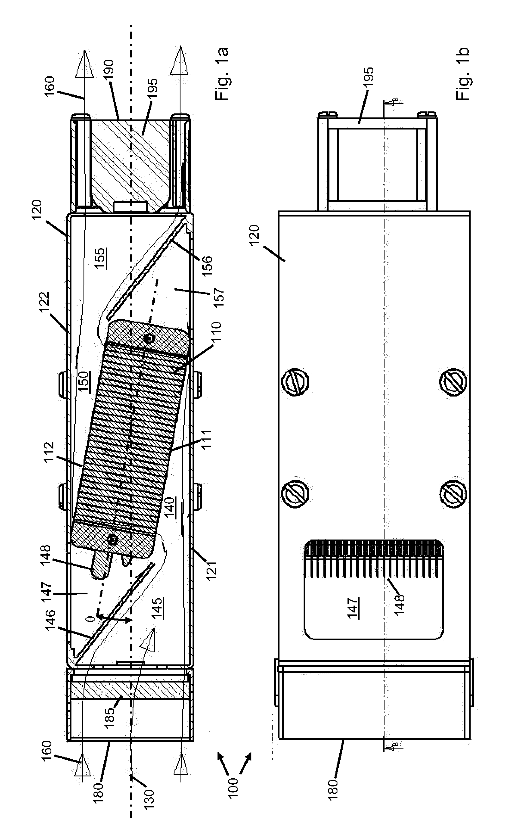
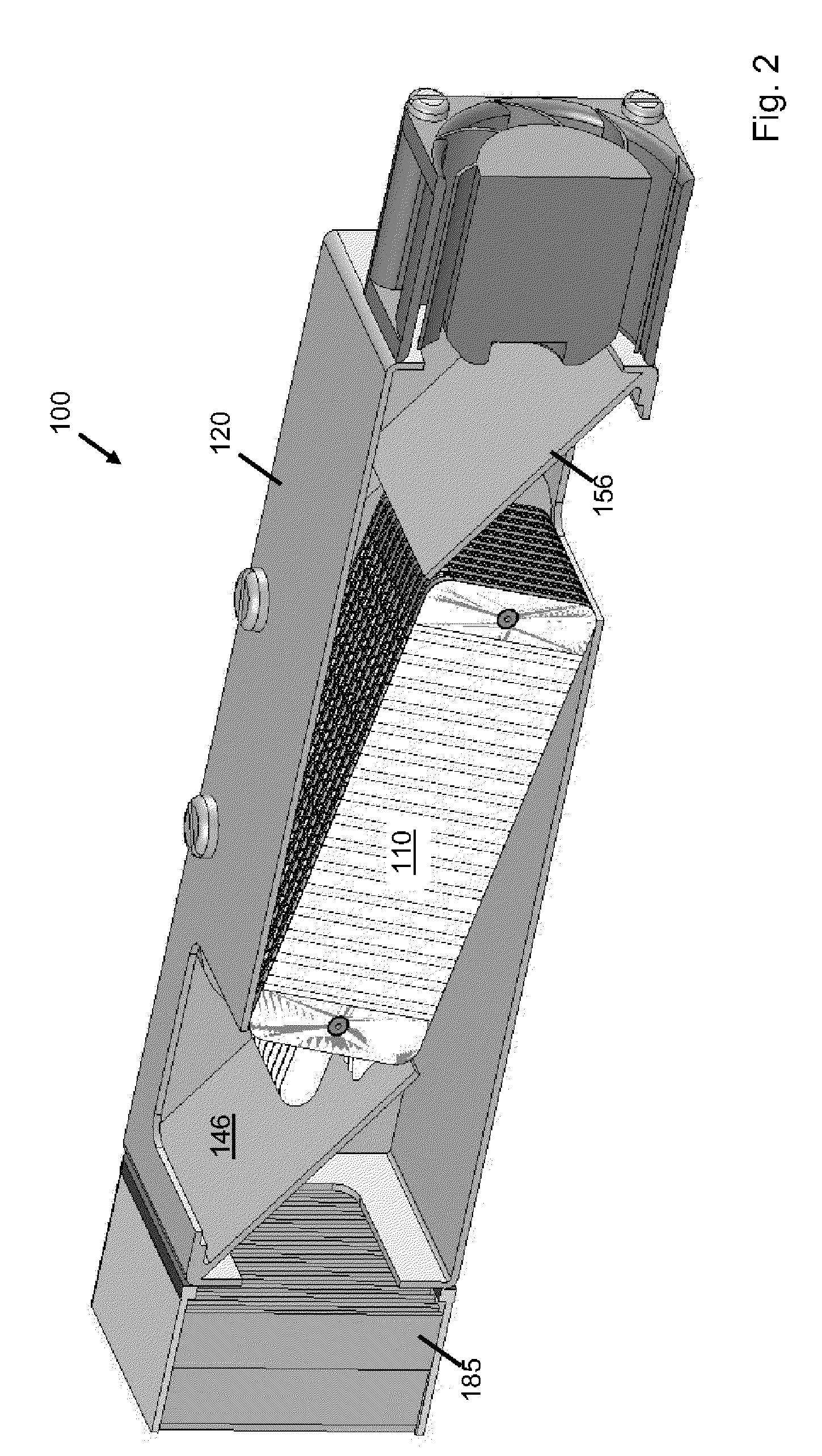
[0035]In the following detailed description of implementations of the present disclosure, reference is made to the accompanying drawings in which like references indicate similar elements, and in which is shown by way of illustration specific implementations in which the present disclosure may be practiced. These implementations are described in sufficient detail to enable those skilled in the art to practice the present disclosure, and it is to be understood that other implementations may be utilized and that logical, mechanical, electrical, functional, and other changes may be made without departing from the scope of the present disclosure. The following detailed description is, therefore, not to be taken in a limiting sense, and the scope of the present disclosure is defined only by the appended claims. As used in the present disclosure, the term “or” shall be understood to be defined as a logical disjunction and shall not indicate an exclusive disjunction unless expressly indica...


PUM

PropertyMeasurementUnit
angleaaaaaaaaaa
angleaaaaaaaaaa
angleaaaaaaaaaa

Abstract

A fuel cell assembly (100) comprising: an enclosure (120) for mounting a fuel cell stack (110) therein, the enclosure comprising an air flow path (160) extending between an air inlet (180) and an air outlet (190); and a fuel cell stack (110) having a plurality of cathode air coolant paths extending between a first face (111) and an opposing second face (112) of the stack, wherein the fuel cell stack is mounted within the enclosure to provide a first tapering air volume (140) between the first face of the stack and a first side wall (121) of the enclosure and a second tapering air volume (150) between the second face of the stack and a second opposing side wall (122) of the enclosure.

Description

RELATED APPLICATION[0001]This application claims the benefit of and priority to United Kingdom Application Serial No. 0818320.4, filed Oct. 7, 2008, the contents of which are incorporated by reference herein in its entirety.BACKGROUND[0002]1. Field[0003]The present disclosure relates to fuel cell assemblies, in particular to enclosures for mounting open cathode fuel cell stacks.[0004]2. General Background[0005]Conventional electrochemical fuel cells convert fuel and oxidant, generally both in the form of gaseous streams, into electrical energy and a reaction product. A common type of electrochemical fuel cell for reacting hydrogen and oxygen comprises a polymeric ion (proton) transfer membrane, with fuel and air being passed over each side of the membrane. Protons (i.e. hydrogen ions) are conducted through the membrane, balanced by electrons conducted through a circuit connecting the anode and cathode of the fuel cell. To increase the available voltage, a stack may be formed compris...

Claims


Application Information

Patent Timeline
Patent Type & Authority Applications(United States)
IPC IPC(8): H01M8/04
CPCH01M8/04014H01M8/2475Y02E60/50H01M2008/1095H01M8/2485H01M8/2484H01M8/02
Inventor HOOD, PETER DAVIDARIKARA, MURALIDHARAN
Owner HOOD PETER DAVID
Why Eureka
Try Eureka