
Method of operating a communication system

a communication system and communication system technology, applied in the field of telecommunications systems, can solve the problems of inability to provide certain operators with services, inability to provide user services, and inability to meet the needs of users, and achieve the effect of improving recovery

Active Publication Date: 2010-04-08
SAMSUNG ELECTRONICS CO LTD
View PDF1 Cites 25 Cited by
  • Summary
  • Abstract
  • Description
  • Claims
  • Application Information

AI Technical Summary

Benefits of technology

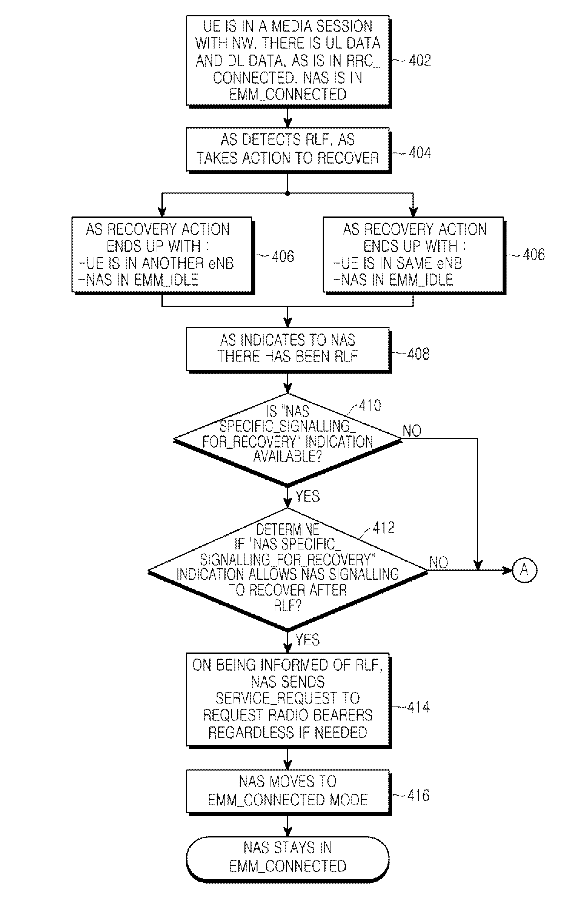
[0034]An aspect of the present invention is to address at least the above-mentioned problems and / or disadvantages and to provide at least the advantages described below. Accordingly, an aspect of the present invention is to provide a method for improved recovery from a Radio Link Failure (RLF).

Problems solved by technology

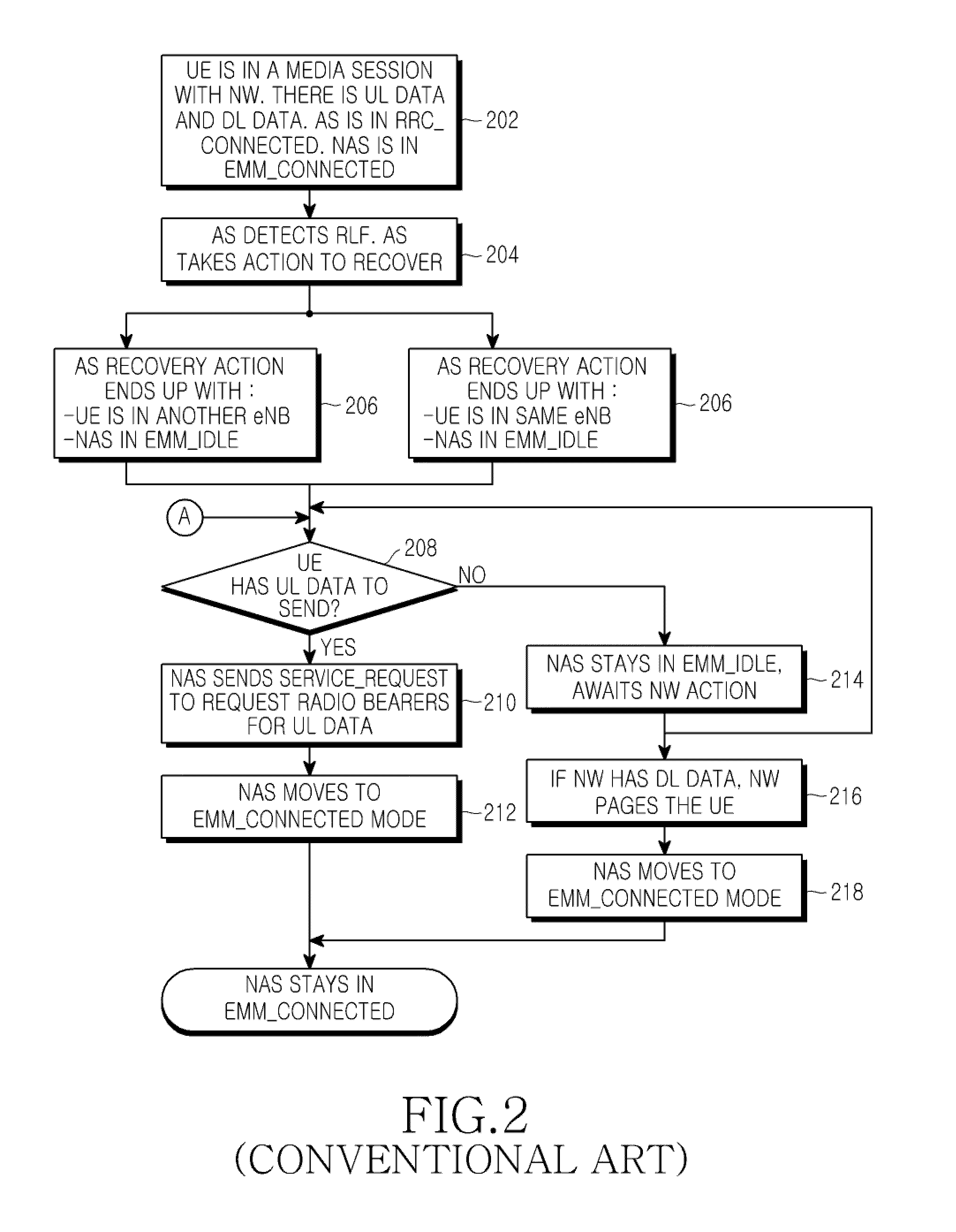
However, an issue arises in the event of a Radio Link Failure (RLF).
More particularly, an issue arises regarding how the system should respond to an RLF, and what steps, if any, should be taken in order to re-establish a connection.
However, this is only likely if the UE had pending Up Link (UL) data.
That may be unacceptable to certain operators because it involves too long a delay or due to other problems.
From the above examples and discussion of the identified problems, it will be appreciated that some of these techniques post-RLF may result in an unacceptable service for the user.
On the other hand, non-GBR services can, by their nature, suffer seconds of interruption.3. The complexities may not outweigh the gain.
There is no certainty, however, that there will be DL data.5. Performing the NAS signalling after detection of a RLF will cause a large signalling spike in certain conditions, for example in the situation where a trainload of users go into and then come out of a tunnel.
Thus, automatic performance of NAS restoration procedures after a RLF can have disadvantages associated with it and adoption of such a procedure may not suit all operators and all situations.

Method used


Image

  • Method of operating a communication system
  • Method of operating a communication system
  • Method of operating a communication system

Examples


Embodiment Construction

[0048]The following description with reference to the accompanying drawings is provided to assist in a comprehensive understanding of exemplary embodiments of the invention as defined by the claims and their equivalents. It includes various specific details to assist in that understanding but these are to be regarded as merely exemplary. Accordingly, those of ordinary skill in the art will recognize that various changes and modifications of the embodiments described herein can be made without departing from the scope and spirit of the invention. In addition, descriptions of well-known functions and constructions are omitted for clarity and conciseness.

[0049]The terms and words used in the following description and claims are not limited to the bibliographical meanings, but, are merely used by the inventor to enable a clear and consistent understanding of the invention. Accordingly, it should be apparent to those skilled in the art that the following description of exemplary embodime...


PUM


Abstract

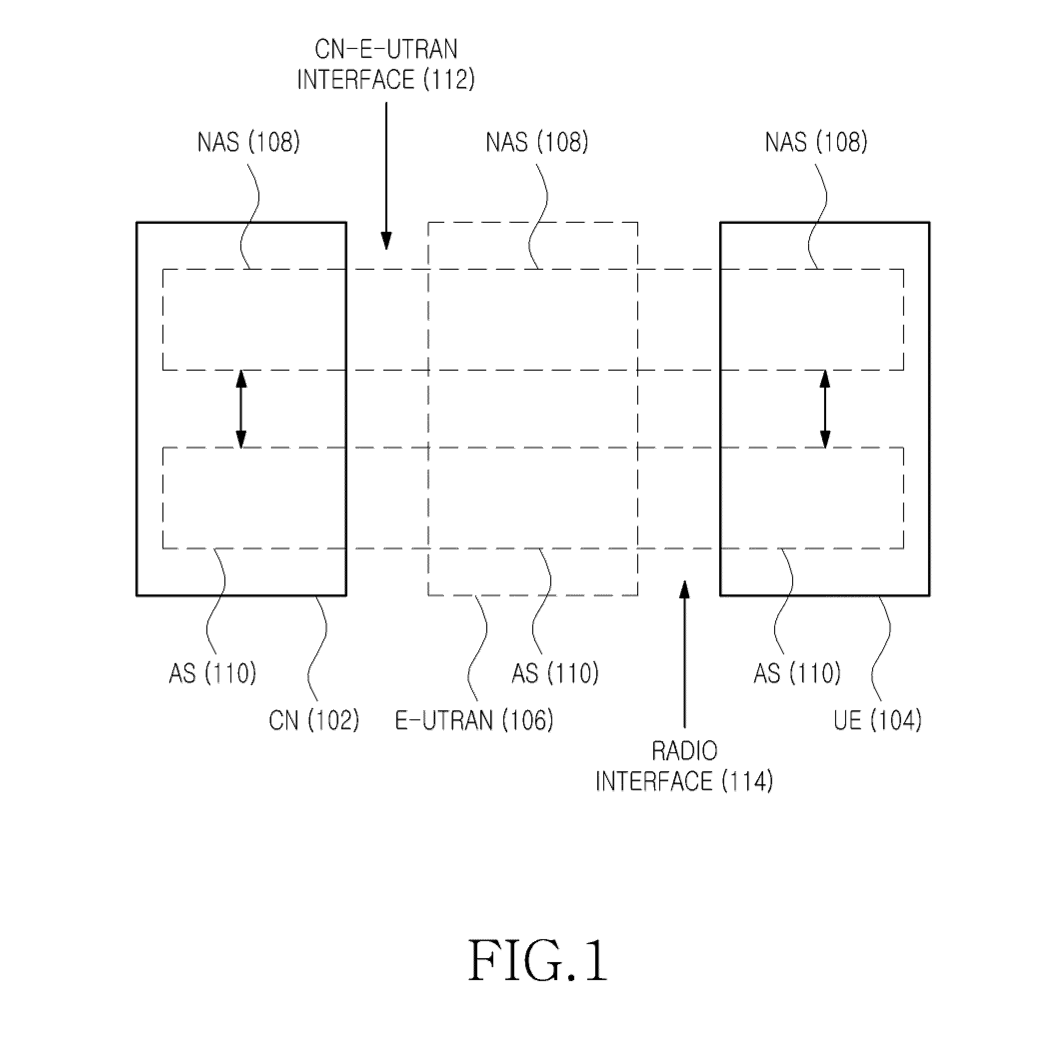
A method of operating a communication system is provided. The communication system comprises a NetWork (NW) and User Equipment (UE), a Non Access Stratum (NAS) via which the NW and UE communicate with each other, and an Access Stratum (AS) providing a physical connection to enable the NAS communication between the NW and UE to be achieved, the physical connection including a wireless radio link to the UE. The method includes sending information from the NW to the UE to determine at least one action of the UE in response to a failure of a radio link to the UE, detecting a Radio Link Failure (RLF), in response to the detecting of the RLF, deciding on an action to be performed by the UE according to the received information, and performing, by the UE, the decided action.

Description

PRIORITY[0001]This application claims the benefit under 35 U.S.C. §119(a) of a patent application filed on Oct. 6, 2008 in the United Kingdom Intellectual Property Office and assigned Serial No. 0818243.8, the entire disclosure of which is hereby incorporated by reference.BACKGROUND OF THE INVENTION[0002]1. Field of the Invention[0003]The present invention relates to a telecommunications system. More particularly, the present invention relates to a method and apparatus for recovering a radio link after Radio Link Failure (RLF) in a telecommunications system.[0004]2. Background to the Invention:[0005]Communication systems (which may also be described as telecommunications systems) that provide wireless connections to mobile User Equipment (UE) are well known and have a variety of configurations. Research and development of communication systems is ongoing, especially in the field of technical specifications for so-called Third Generation Partnership Project (3GPP) systems.[0006]In th...

Claims


Application Information

Patent Timeline
Patent Type & Authority Applications(United States)
IPC IPC(8): H04W72/00
CPCH04W76/028H04W76/19H04W76/10
Inventor BISHOP, CRAIGCHIN, CHEN-HO
Owner SAMSUNG ELECTRONICS CO LTD
Learn More