Cyclonic separation device for vacuum cleaner

a cyclonic separation and vacuum cleaner technology, applied in the direction of cleaning equipment, separation processes, vortex flow apparatus, etc., can solve the problems of low efficiency of the primary cyclonic separation device, inconvenient large volume, filter device, etc., and achieve the effect of reducing the volume of the whole machine and increasing the separation efficiency

Inactive Publication Date: 2010-04-15
CHANGZHOU SHINRI HOUSEHOLD APPLIANCE MFG
View PDF29 Cites 27 Cited by
  • Summary
  • Abstract
  • Description
  • Claims
  • Application Information

AI Technical Summary

Benefits of technology

[0006]The object of the present invention is to provide a cyclonic separation device for vacuum cleaner in which both filter and cyclonic separators are integrated to increase separation efficiency and reduce the volume of whole machine.

Problems solved by technology

The disadvantages of this type of cyclonic filter separation devices are as follows: although part of dust is separated by the cyclone, the airflow will likely bring the subsided dust to the upward air again; thus the upward air containing a large amount of dust will block the filter device, which requires frequent cleanings.
However, this type of devices has some common disadvantages: low efficiency of the primary cyclonic separation device and inconvenient large volume due to the extra secondary cyclonic devices.

Method used


Image

  • Cyclonic separation device for vacuum cleaner
  • Cyclonic separation device for vacuum cleaner
  • Cyclonic separation device for vacuum cleaner

Examples


first embodiment

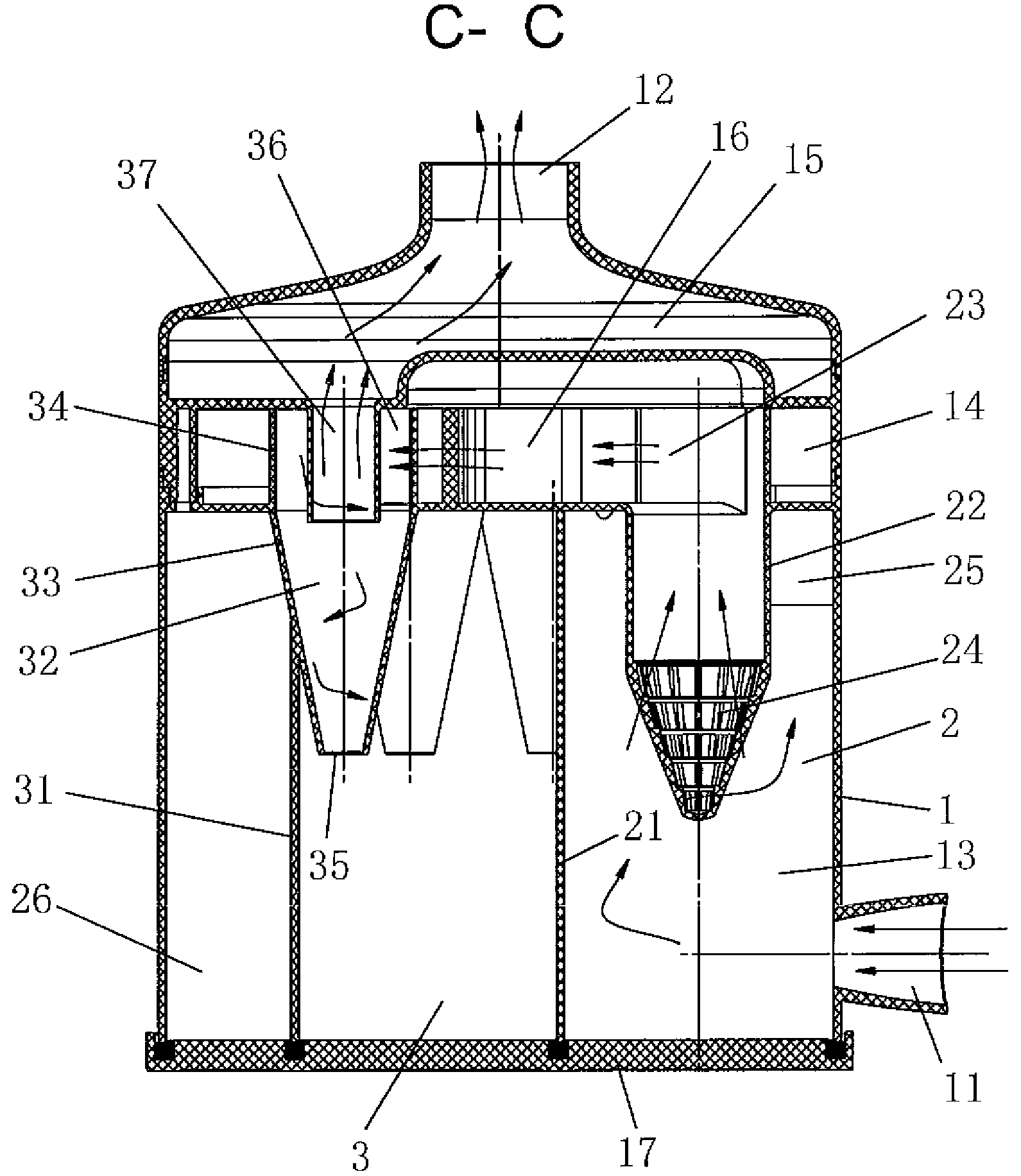
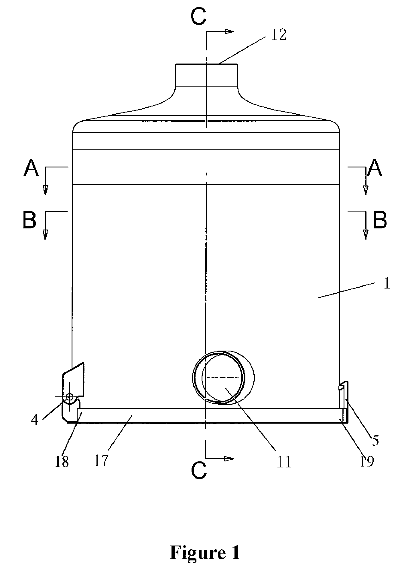
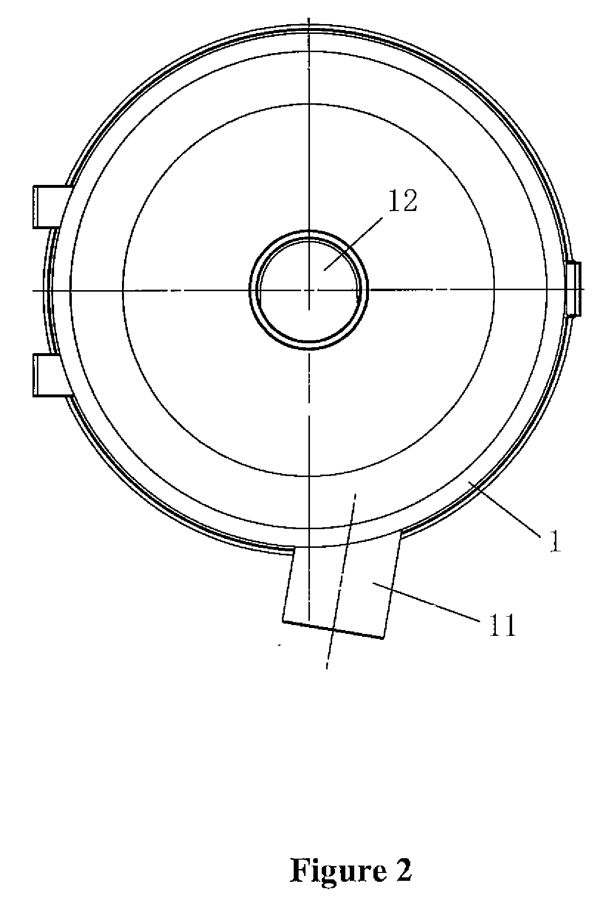
[0038]The with reference to FIGS. 1, 2, 3, 4, 5 and 6, a cyclonic separation device for vacuum cleaner comprising: a external barrel 1 having a main wind inlet 11 and a main wind outlet 12; a primary separator 2 and a secondary separator 3 in communication with each other both of which are located in the external barrel 1, and the primary separator 2 is connected to the main wind inlet 11 when the secondary separator 3 is connected to the main wind outlet 12;

[0039]from the top to the bottom, the external barrel 1 is divided into a separation chamber 13, a connection chamber 14 and an out-wind chamber 15; and the main wind inlet 11 is located at the lower portion of the separation chamber 13 while main wind outlet 12 is located on the top of the out-wind chamber 15;

[0040]the primary separator 2 includes a primary cyclonic barrel 21 located in the separation chamber 13, the main wind inlet 11 is connected with the primary cyclonic barrel 21 along its tangential direction; a primary w...

second embodiment

[0046]The with reference to FIGS. 7, 8, 9, 10 and 11, a cyclonic separation device for vacuum cleaner comprising: a external barrel 1 having a main wind inlet 11 and a main wind outlet 12; a primary separator 2 and a secondary separator 3 in communication with each other both of which are located in the external barrel 1, and the primary separator 2 is connected to the main wind inlet 11 when the secondary separator 3 is connected to the main wind outlet 12;

[0047]from the top to the bottom, the external barrel 1 is divided into a separation chamber 13, a connection chamber 14 and an out-wind chamber 15; and the main wind inlet 11 is located at the lower portion of the separation chamber 13 while main wind outlet 12 is located on the top of the out-wind chamber 15;

[0048]the primary separator 2 includes a primary cyclonic barrel 21 located in the separation chamber 13, the main wind inlet 11 is connected with the primary cyclonic barrel 21 along its tangential direction; a primary wi...

third embodiment

[0053]The with reference to FIGS. 12, 13, 14 and 15, a cyclonic separation device for vacuum cleaner comprising: a external barrel 1 having a main wind inlet 11 and a main wind outlet 12; a primary separator 2 and a secondary separator 3 in communication with each other both of which are located in the external barrel 1, and the primary separator 2 is connected to the main wind inlet 11 when the secondary separator 3 is connected to the main wind outlet 12;

[0054]from the top to the bottom, the external barrel 1 is divided into a separation chamber 13, a connection chamber 14 and an out-wind chamber 15; and the main wind inlet 11 is located at the lower portion of the separation chamber 13 while main wind outlet 12 is located on the top of the out-wind chamber 15;

[0055]the primary separator 2 includes a primary cyclonic barrel 21 located in the separation chamber 13, the main wind inlet 11 is connected with the primary cyclonic barrel 21 along its tangential direction; a primary win...


PUM

PropertyMeasurementUnit
forceaaaaaaaaaa
volumeaaaaaaaaaa
shapeaaaaaaaaaa

Abstract

It is provided in the present invention with a cyclonic separation device for vacuum cleaner comprising a external barrel having a main wind inlet and a main wind outlet; a primary separator and a secondary separator in communication with each other both of which are located in the external barrel, and the primary separator is connected to the main wind inlet when the secondary separator is connected to the main wind outlet. Both filter and cyclonic separators are integrated in present invention: cyclonic filter device works as the primary separator and cyclonic separation device works as the secondary separator; which increases separation efficiency and reduces the volume of whole machine.

Description

FIELD OF THE INVENTION[0001]The present invention relates to a cyclonic separation device for vacuum cleaner.BACKGROUND OF THE INVENTION[0002]It is well known that cyclonic separation devices have been widely used in different vacuum cleaners. The common cyclonic separation devices work as follows: the inlet of dust-laden airflow is mounted above the cyclone chamber, and the wind outlet (negative pressure source) is mounted on the center of the chamber top; the dust-laden airflow enters into the cyclone chamber along the tangential direction and forms cyclone caused by centrifugal force, and part of dust subsides down to bottom when the dedusted air flows upwards through the filter device, then is expelled out via the wind outlet on the top (e.g. WO98 / 35602).[0003]The disadvantages of this type of cyclonic filter separation devices are as follows: although part of dust is separated by the cyclone, the airflow will likely bring the subsided dust to the upward air again; thus the upwa...

Claims


Application Information

Patent Timeline
Patent Type & Authority Applications(United States)
IPC IPC(8): B04C5/24B04C5/04
CPCA47L9/1625A47L9/1641A47L9/165B04C3/06B04C2009/004B04C5/185B04C5/28B04C7/00B04C5/12
Inventor ZHOU, LIQUN
Owner CHANGZHOU SHINRI HOUSEHOLD APPLIANCE MFG
Why Eureka
Try Eureka