Supercharge Your Innovation With Domain-Expert AI Agents!

Active gauge protection for drill bits

a drill bit and active technology, applied in the field of drill bits, can solve the problems of severely damaging the cutting elements of the drill bit, the drill bit may begin to move off-center from the center of the borehole, and the drill bit may begin to move off-center, so as to minimize the damage to the gauge cutter and minimize the gouging of the casing wall

Inactive Publication Date: 2010-04-15
ULTERRA DRILLING TECH LP
View PDF3 Cites 8 Cited by
  • Summary
  • Abstract
  • Description
  • Claims
  • Application Information

AI Technical Summary

Benefits of technology

[0006]Apparatus and methods are disclosed to protect for the cutting elements, specifically the gauge cutters, from coming into contact with the borehole casing during both traversal down the hole and during drill out operations. For example, dynamic forces, including “whirl”, may cause the drill bit to either rotate off-center in the borehole or rotate in a diameter beyond the gauge diameter of the bit. The protective inserts of the present invention may prevent the cutting elements of the bit from coming into contact with the borehole casing by acting as a first point of impact for the bit, to minimize damage to the gauge cutters. The protective inserts may also minimize gouging of the casing wall by acting as a smooth bearing surface during bit rotation. The protective inserts of the present invention may act as an additional gauge after abrasion wears the invention down to gauge diameter.
[0008]A method of protecting a gauge cutter of a drill bit having a selected gauge diameter and operable to be positioned within a casing positioned within a rock formation, the casing comprising an casing inner wall having a casing inner diameter greater than the gauge diameter, wherein the positioning of the drill bit within the casing defines a drift distance corresponding to the distance between the gauge diameter and the casing inner diameter, is disclosed. The method includes the steps of coupling a protective insert to the drill bit such that a portion of the protective insert extends beyond the gauge diameter by a selected overgauge distance, positioning the drill bit within the casing, and preventing the gauge cutter from contacting the casing inner wall along a selected length of the casing.

Problems solved by technology

One significant problem that may occur during drill out is that the drill bit, upon initial contact with the shoe, may begin to move off-center from the center of the borehole.
Under such conditions, an unprotected drill bit may continue to spin outside its designed gauge diameter and eventually come into contact with the casing, severely damaging the cutting elements of the drill bit.
A drill bit spinning at normal operational speed may contact the borehole wall with tremendous force.
This contact may cause several events to occur.
For example, the drill bit may remain unstable and possibly build up more instability, causing it to wander off the intended drill path or drill at awkward angles.
The cutters, especially the gauge cutters, may become directly exposed to the casing wall and impact the casing, leading to chipped, cracked, or complete destruction of the face of the cutting element, which may fail under a sudden shock impact.
The casing wall itself may become scarred or gouged by the impact of the cutters, which are typically made of a very hard material that can cut through metal (such as polycrystalline diamond compact).

Method used


Image

  • Active gauge protection for drill bits
  • Active gauge protection for drill bits
  • Active gauge protection for drill bits

Examples


Embodiment Construction

[0014]Refer now to the drawings wherein depicted elements are not necessarily shown to scale and wherein like or similar elements are designated by the same reference numeral through the several views.

[0015]As used herein, the terms “up” and “down”; “upper” and “lower”; “uphole” and “downhole” and other like terms indicating relative positions to a given point or element are utilized to more clearly describe some elements of the embodiments of the invention. Commonly, these terms relate to a reference point as the surface from which drilling operations are initiated as being the top point and the total depth of the well being the lowest point.

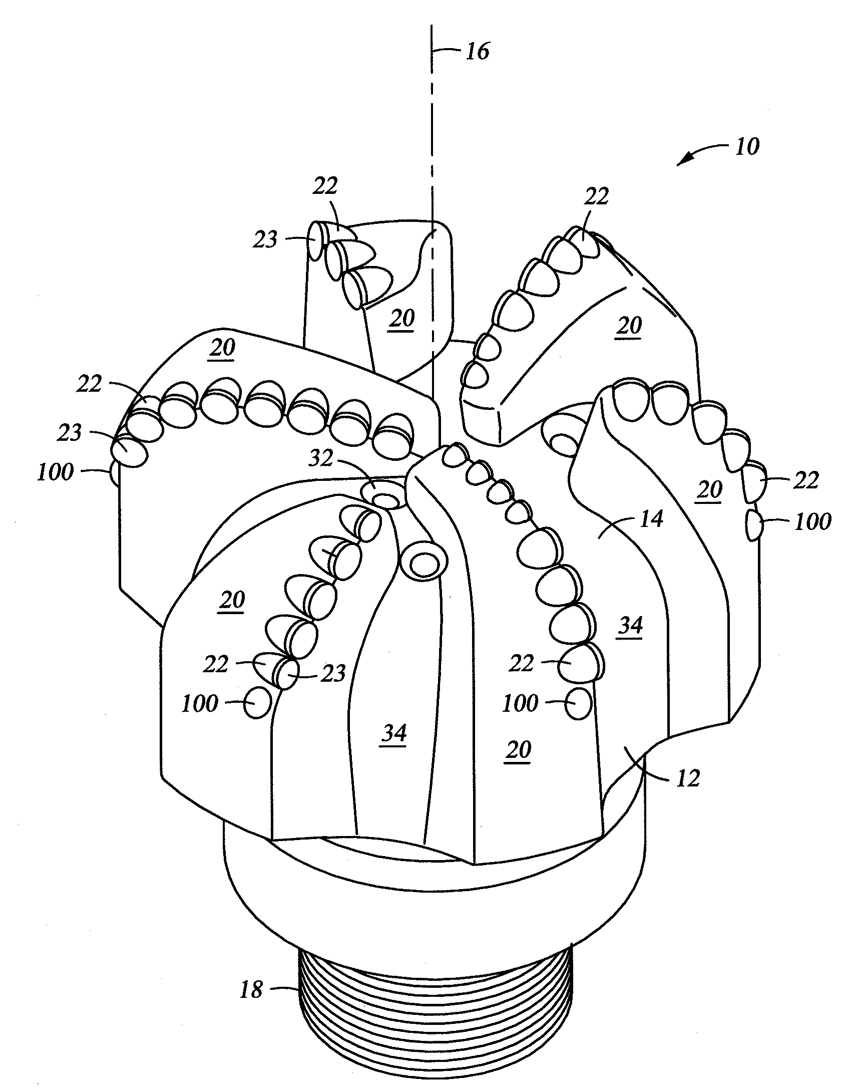
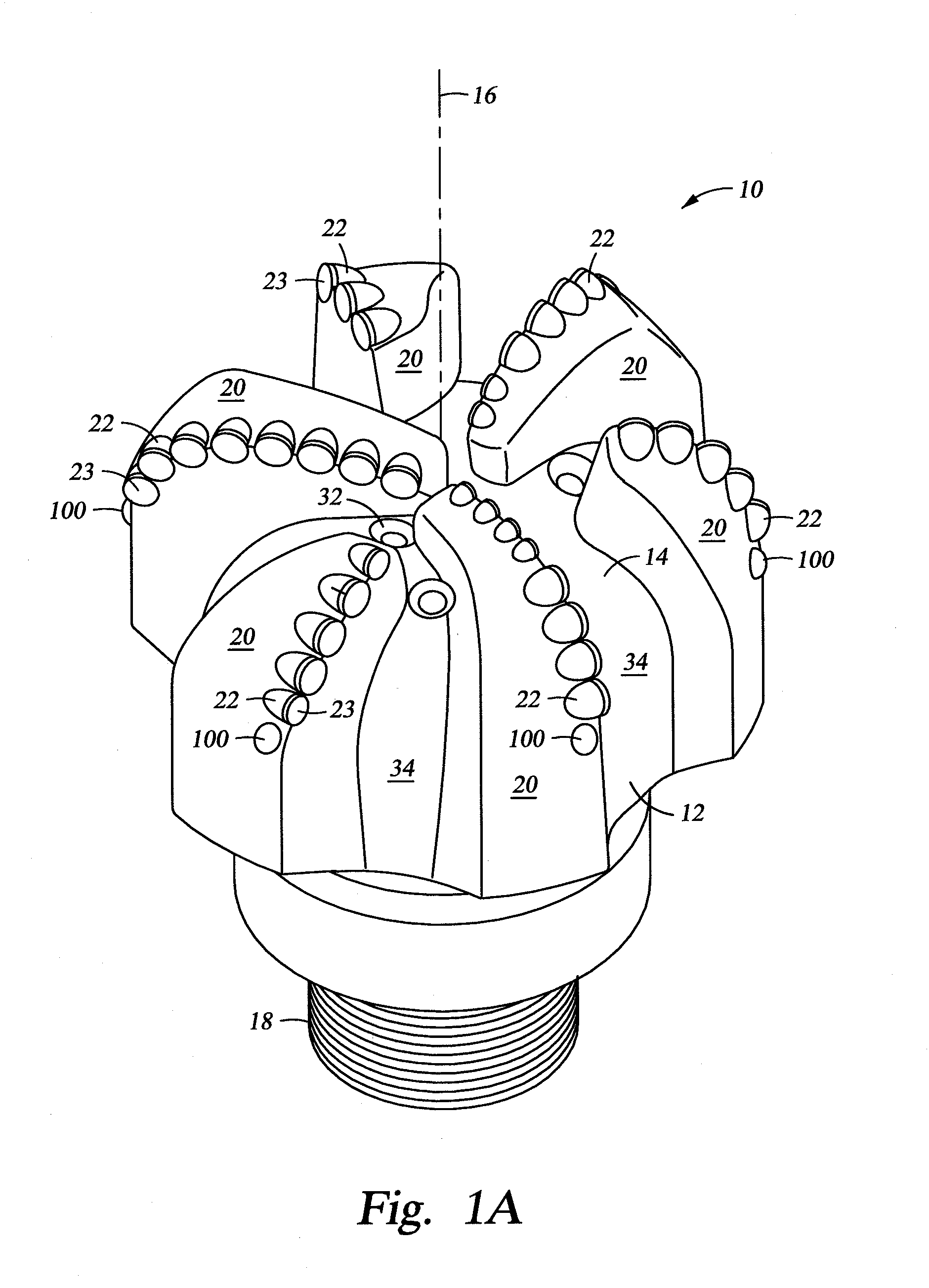
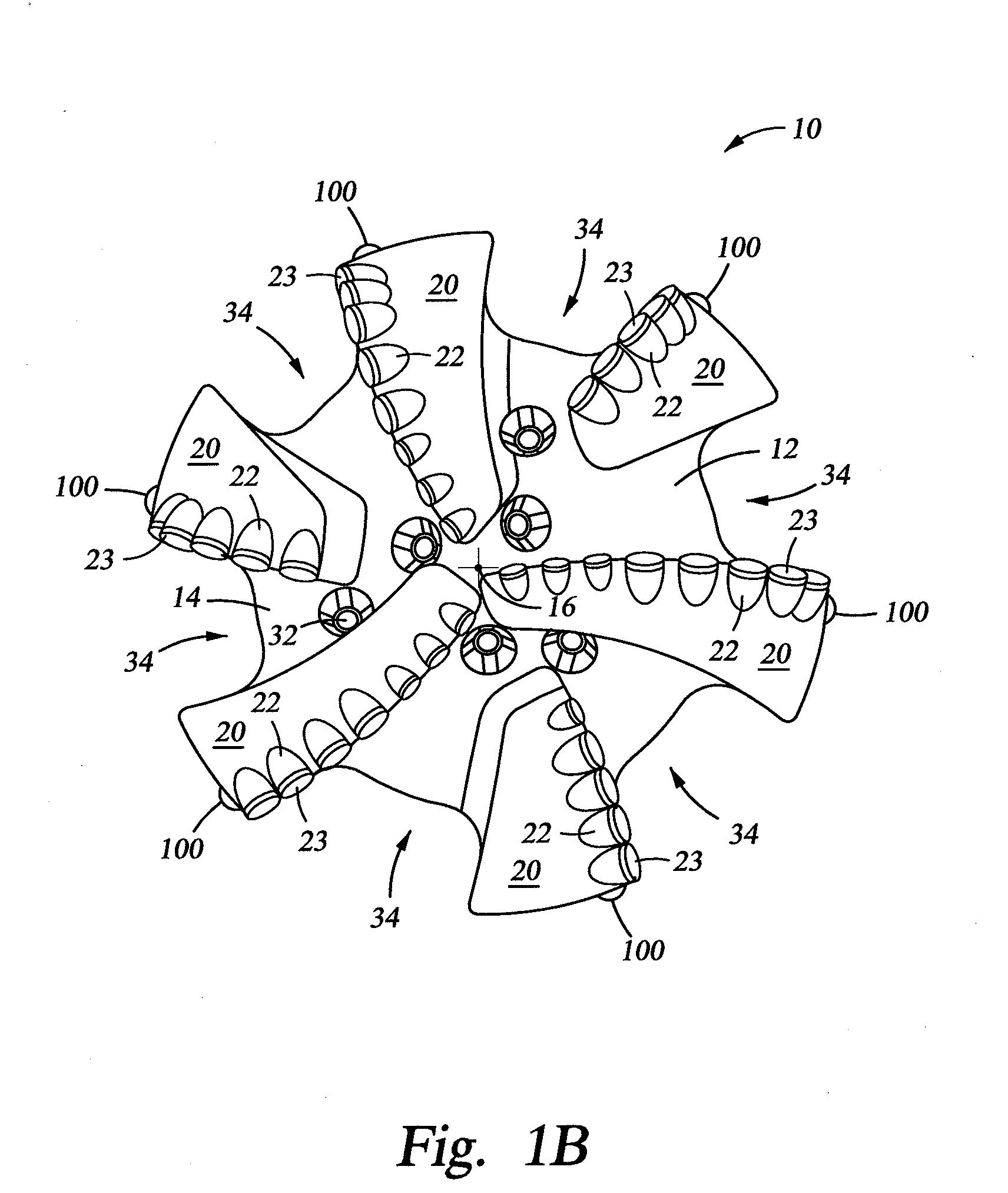
[0016]An apparatus and method to protect the cutting elements of a drill bit, specifically the gauge cutters, from coming into contact with the borehole casing during both traversal down the hole and during drill out operations are disclosed. The drill bit comprises one or more protective inserts that protrude beyond the gauge distance and into...


PUM


Abstract

A drill bit having a selected gauge diameter and operable to be positioned within a casing positioned within a rock formation, the casing comprising an casing inner wall having a casing inner diameter greater than the gauge diameter, wherein the positioning of the drill bit within the casing defines a drift distance corresponding to the distance between the gauge diameter and the casing inner diameter, the drill bit comprising a blade comprising a gauge cutter operable to cut an earth formation at the gauge diameter; and a protective insert coupled the drill bit such that a portion of the protective insert extends beyond the gauge diameter by a selected overgauge distance, wherein the protective insert is operable to engage the casing inner wall to substantially prevent the gauge cutter from engaging the casing inner wall as the drill bit is positioned through a selected length of the casing.

Description

FIELD OF INVENTION[0001]The present invention relates in general to drill bits and, more specifically, to protecting the drill bit and casing from damage during tripping in and drill out operations.BACKGROUND OF INVENTION[0002]A variety of drill bits, including fixed and rotary bits, are used in drilling operations. One part of the drilling operation that occurs before penetration into a formation involves drilling through a concrete pad at the bottom of a borehole called the “shoe”. This operation is called “drill out”, wherein the cement is “tagged up” as the drill bit drills through the structure. Often this pad is formed from the residue of casing operations of the borehole but it may also form from intentional filling the bottom of the borehole with cement. The shoe functions to cap the formation at the bottom of the metal casing until the drilling operator wishes to drill into the formation below the shoe.[0003]One significant problem that may occur during drill out is that th...

Claims


Application Information

Patent Timeline
IPC IPC(8): E21B10/36E21B17/10
CPCE21B17/1092E21B12/04
Inventor MUMMA, MATTHEW D.
Owner ULTERRA DRILLING TECH LP
Features
  • R&D
  • Intellectual Property
  • Life Sciences
  • Materials
  • Tech Scout
  • Unparalleled Data Quality
  • Higher Quality Content
  • 60% Fewer Hallucinations
Learn More