
Pulverizer for food waste treatment apparatus

a technology for food waste and treatment equipment, which is applied in the direction of supporting equipment, gas current separation, grain husking, etc., can solve the problems of increasing the amount of food waste, food waste, and polluting the surrounding air, so as to reduce power consumption, effectively agitate and pulverize food waste input, and minimize the remnants of food waste

Inactive Publication Date: 2010-04-15
WOONGJIN COWAY
View PDF1 Cites 11 Cited by
  • Summary
  • Abstract
  • Description
  • Claims
  • Application Information

AI Technical Summary

Benefits of technology

[0011]Accordingly, the present invention has been made keeping in mind the above problems occurring in the prior art, and an object of the present invention is to provide a pulverizer for food waste apparatuses which has a spherical body and is constructed such that a spiral pulverizing screw is provided in the spherical body, thus more effectively agitating and pulverizing food waste input into the pulverizer, and minimizing remnants of food waste in the pulverizer, thereby reducing power consumption and preventing noise.

Problems solved by technology

This conventional food waste treatment method increases the amount of food waste.
If dumped food waste is not frequently treated, odors may result, with the result that the surrounding air is polluted.
However, because the pulverizing screw is provided on the lower portion of the apparatus, food waste may not be evenly agitated or pulverized, with the result that a grain size of pulverized food waste is relatively large and food waste undesirably lumps at the central portion of the pulverizing screw and thus may not be pulverized.
Furthermore, since a heater for drying food waste is provided in the lower portion of the apparatus, pulverizing and drying performance is reduced.
In addition, a large quantity of food waste is compressed by the rotation of the pulverizing screw.
Thereby, an overload is applied to the pulverizing screw, with the result that it may become stopped.
Furthermore, there is a disadvantage in that the amount of food waste which can be input into the pulverizer is reduced because of the large volume ratio occupied by the pulverizing screw related to the volume of the pulverizer.
Thus, odors which result from the process of treating the food waste may be disagreeable to the user.

Method used


Image

  • Pulverizer for food waste treatment apparatus
  • Pulverizer for food waste treatment apparatus
  • Pulverizer for food waste treatment apparatus

Examples


first embodiment

[0060]the present invention will be described in detail with reference to the related drawings.

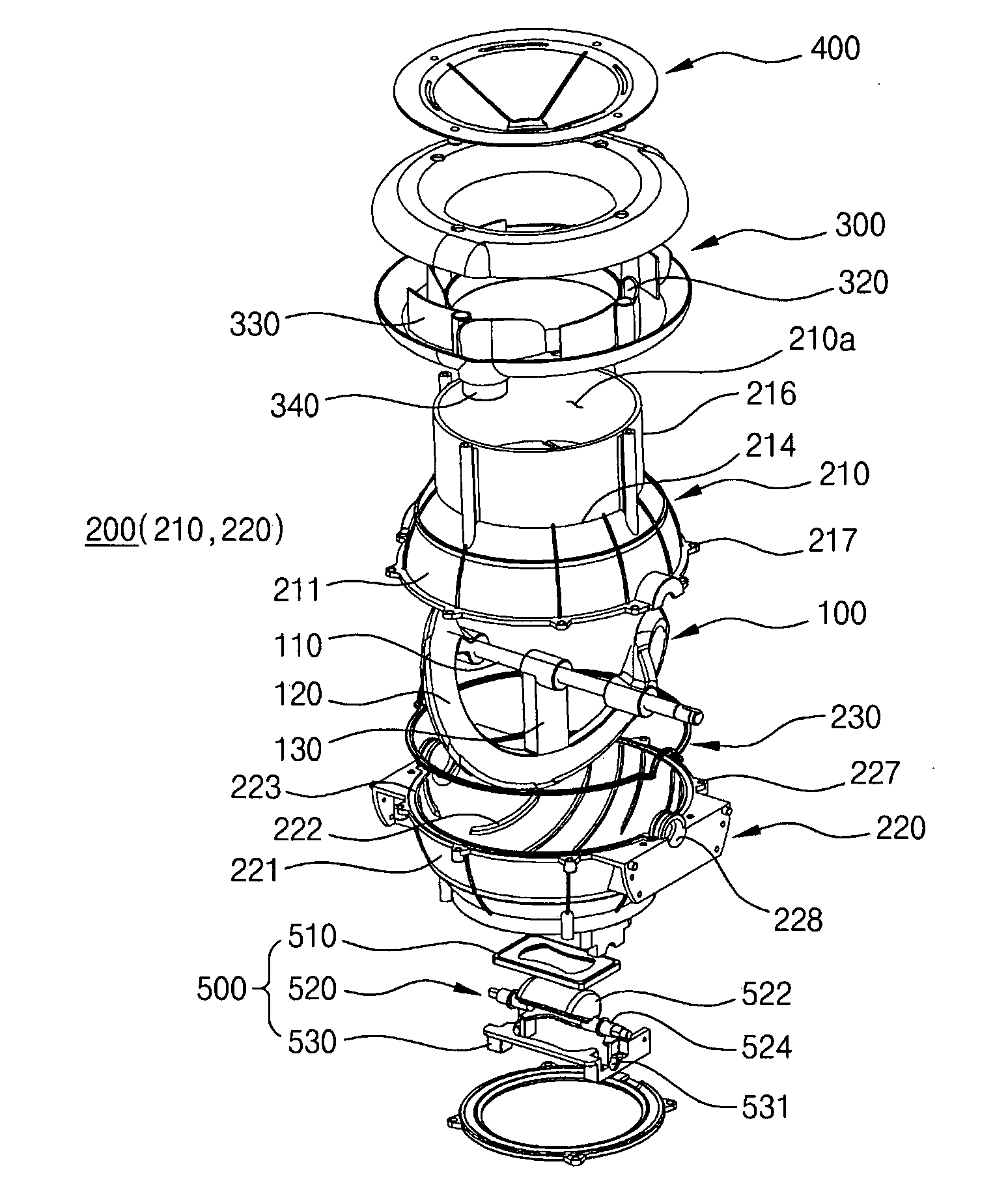
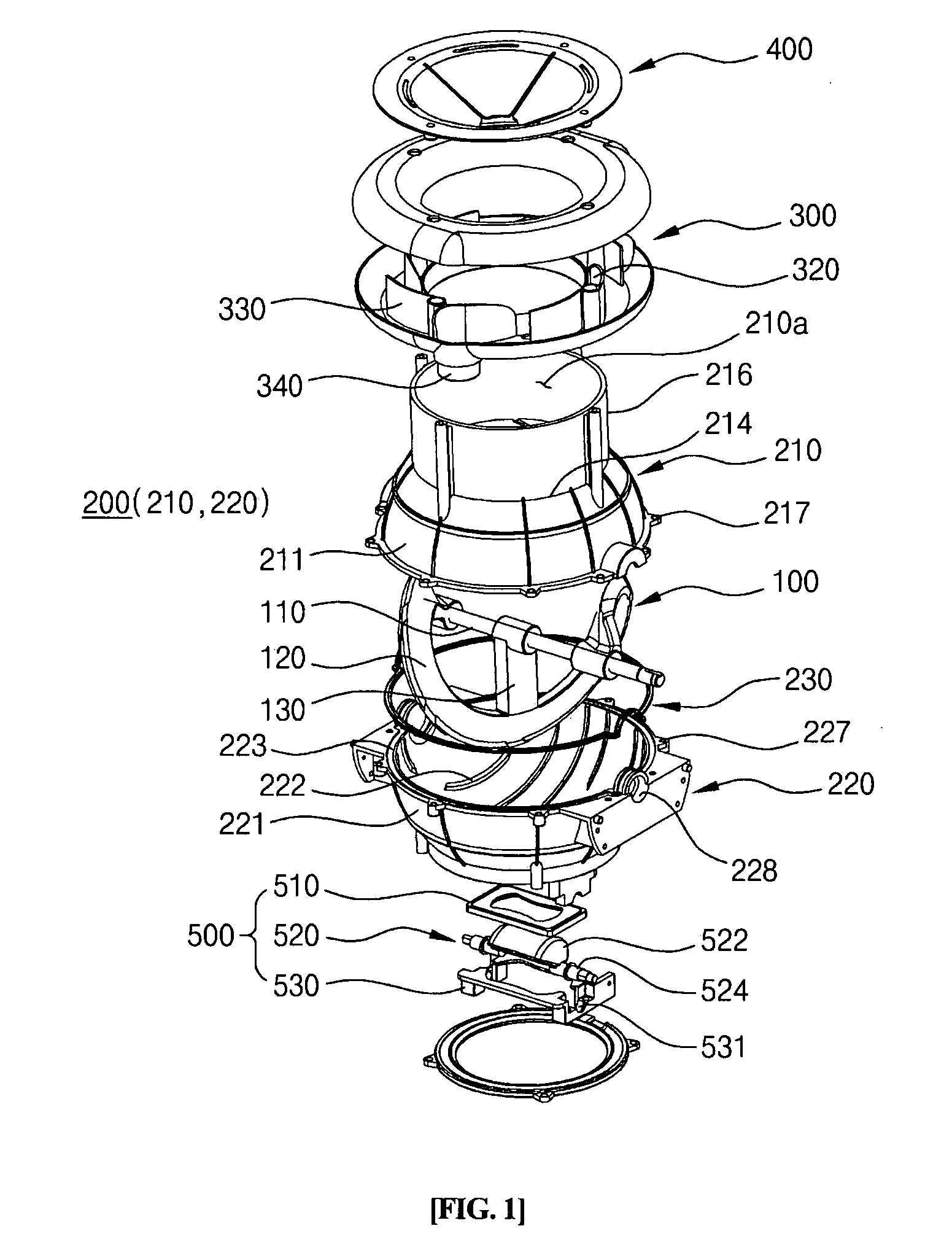
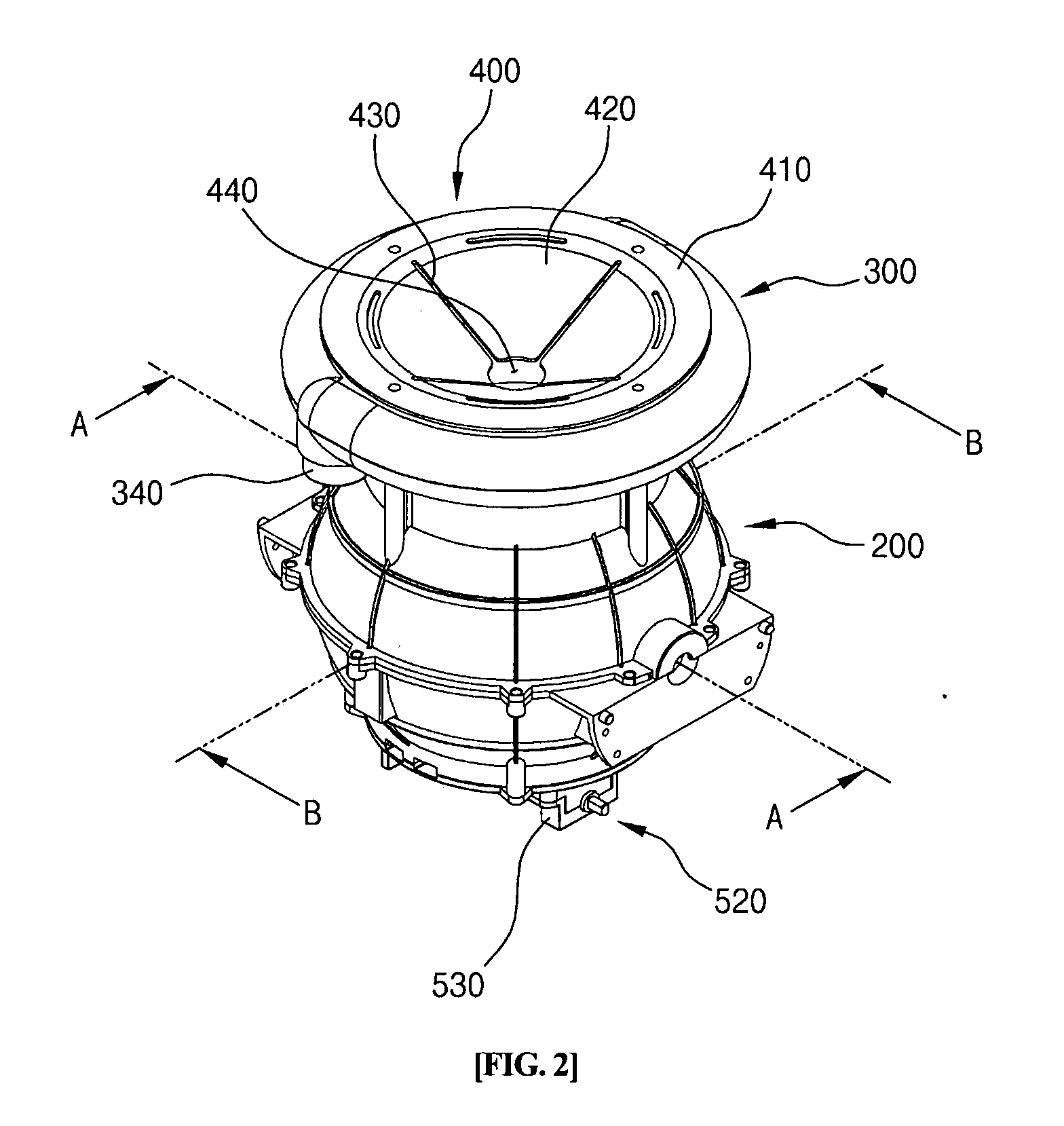
[0061]FIG. 1 is an exploded perspective view of the pulverizer for food waste treatment apparatuses, according to the first embodiment of the present invention. FIG. 2 is an upper perspective view of a pulverizer for a food waste treatment apparatus, according to a first embodiment of the present invention. FIG. 3 is a bottom perspective view of the pulverizer of FIG. 2. FIG. 4 is a plan view illustrating the pulverizer of FIG. 2. FIG. 5 is a front view illustrating the pulverizer of FIG. 2. FIG. 6 is a right side view illustrating the pulverizer of FIG. 2. FIG. 7 is a bottom view illustrating the pulverizer of FIG. 2.

[0062]Referring to FIGS. 1 through 7, the pulverizer according to the first embodiment of the present invention includes a hollow pulverizing casing 200, a pulverizing screw 100 which is installed in the pulverizing casing 200 so as to be rotatable, an exhaust channel unit 30...

second embodiment

[0109]In the second embodiment, cutting notches 125 having predetermined depths are formed in an outer cutting edge of a drive blade 120 constituting the pulverizing screw 100′. The shape of each cutting notch 125 is determined along a circumference of an imaginary circle which is defined around the central axis of a rotating shaft 110 and has a predetermined radius. In other words, according to the intended purposes of a designer, various numbers of cutting notches 125 may be formed in the drive blade 120 along the circumferences of imaginary concentric circles which are formed around the central axis of the rotating shaft 110 and have different radii.

[0110]Pulverizing protrusions 222′ corresponding to the cutting notches 125 of the drive blade 120 are provided on the circumferential inner surface of the lower pulverizing casing 220′. The pulverizing protrusions 222′ are provided on at least one concentric circle at positions spaced apart from each other at regular or irregular int...


PUM


Abstract

The present invention provides a pulverizer of a food waste treatment apparatus. The pulverizer of the present invention includes a main body, a pulverizing screw and an exhaust channel unit. The main body has a hollow space therein. The pulverizing screw includes a rotating shaft which is installed in the main body so as to be rotatable, and at least one drive blade which extends from the rotating shaft. The exhaust channel unit has an annular shape and is coupled to the upper end of the main body. An intake hole and an exhaust hole are formed through the outer surface of the exhaust channel unit. Furthermore, a cover may be removably coupled to the upper end of the exhaust channel unit.

Description

BACKGROUND OF THE INVENTION[0001]1. Field of the Invention[0002]The present invention relates generally to a pulverizer for a food waste treatment apparatus and, more particularly, to a pulverizer for a food waste treatment apparatus in which a spiral pulverizing screw is provided in a spherical body to reliably agitate and pulverize food waste, and an exhaust channel unit is provided on the spherical body to effectively vent exhaust gas generated by the treatment of food waste.[0003]2. Description of the Related Art[0004]Generally, every house, restaurant, etc. discharges a predetermined amount of food waste everyday. Typically, such food waste is dumped after only water is removed from the food waste using a filter or the like. This conventional food waste treatment method increases the amount of food waste. If dumped food waste is not frequently treated, odors may result, with the result that the surrounding air is polluted.[0005]To effectively reduce and recycle food waste, the ...

Claims


Application Information

Patent Timeline
Patent Type & Authority Applications(United States)
IPC IPC(8): B02C23/36B02C18/16E03C1/266
CPCE03C1/266B02C19/00B09B3/00
Inventor SIM, SANG GUPARK, YOUNG DONKIM, SUNG JIN
Owner WOONGJIN COWAY
Learn More