Poppet valve assembly, system, and apparatus for use in high speed compressor applications

a high-speed compressor and poppet valve technology, applied in the field of high-speed compressors, can solve the problems that the conventional poppet valve assembly of these conventional compressors does not allow precise control of fluid flow

Inactive Publication Date: 2010-04-15
COMPRESSOR ENG CORP
View PDF29 Cites 385 Cited by
  • Summary
  • Abstract
  • Description
  • Claims
  • Application Information

AI Technical Summary

Benefits of technology

[0006]The present disclosure relates generally to a valve assembly that includes miniature poppets which may be utilized with high-speed compressor applications. One of the broader forms of invention may provide a poppet valve assembly, the poppet valve assembly including a cage that includes a plurality of counter bores disposed therein. The poppet valve assembly further includes a plurality of poppets, each poppet having a stem and a head. The head of each poppet has a maximum diameter that is less than approximately one inch. The stem of the poppet is disposed in a corresponding one of the said plurality of counter bores. The poppet valve assembly also includes a seat plate overlying said cage, said seat plate including a plurality of through bores axially aligned with the plurality of counter bores of the cage, wherein each of the plurality of through bores is sized to have a smaller diameter than the maximum diameter of the head. A lift spacer is disposed in each of the counter bores.
[0007]According to another of the broader forms of the invention may provide an apparatus that includes a poppet valve assembly, the poppet valve assembly including a cage that includes a plurality of counter bores disposed therein. The poppet valve assembly further includes a plurality of poppets, each poppet having a stem and a head. The head of each poppet has a maximum diameter that is l...

Problems solved by technology

The size of such conventional poppets in the valve assemblies of these conventional compressors does not allow for precise c...

Method used


Image

  • Poppet valve assembly, system, and apparatus for use in high speed compressor applications
  • Poppet valve assembly, system, and apparatus for use in high speed compressor applications
  • Poppet valve assembly, system, and apparatus for use in high speed compressor applications

Examples


Embodiment Construction

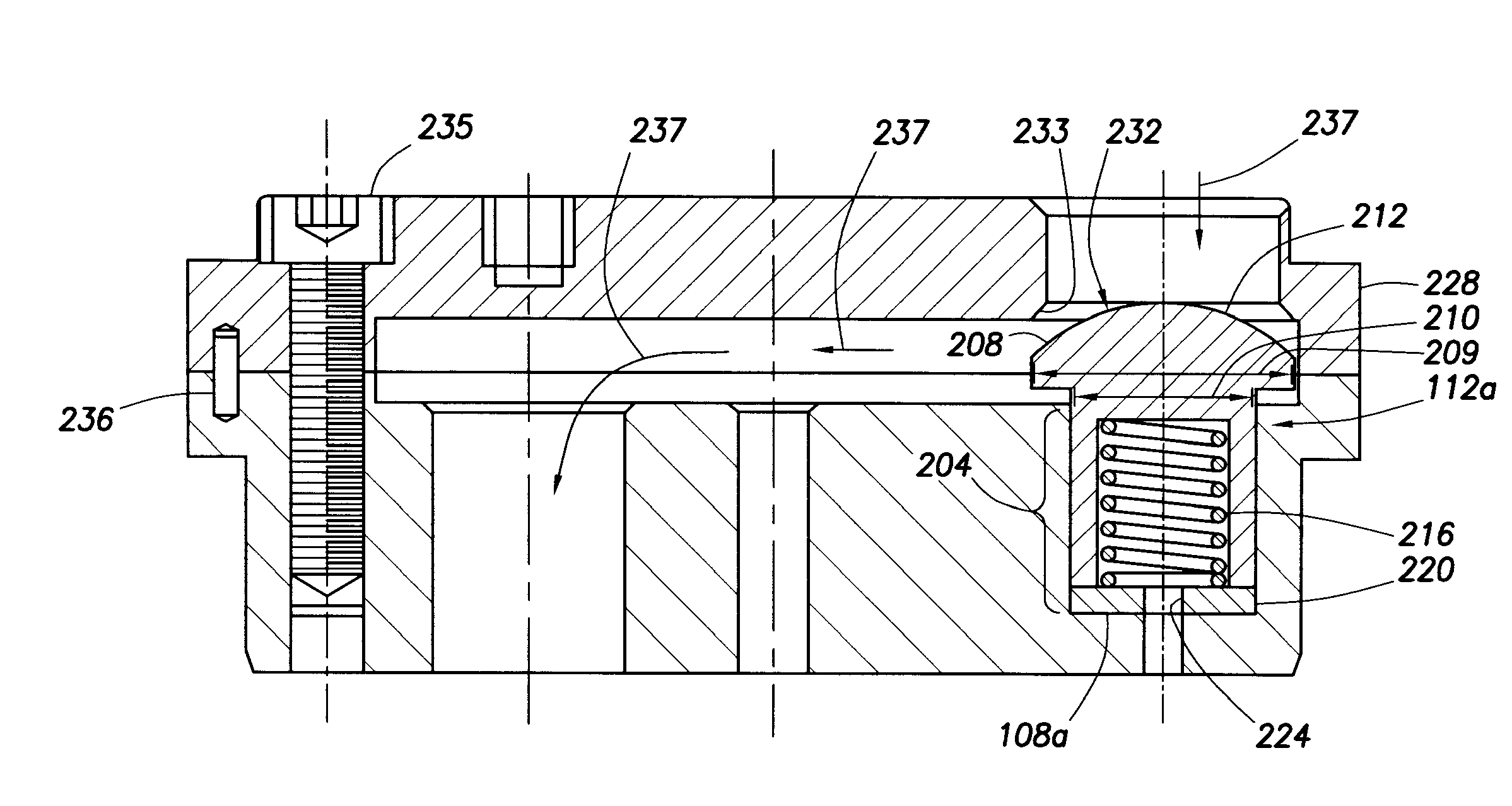
[0012]The present disclosure relates generally to a valve assembly that includes miniature poppets which may be utilized with high-speed compressor applications. It is understood, however, that specific embodiments are provided as examples to teach the broader inventive concept, and one of ordinary skill in the art can easily apply the teaching of the present disclosure to other methods or apparatus. Also, it is understood that the apparatus discussed in the present disclosure includes some conventional structures. Since these structures are well known in the art, they will only be discussed in a general level of detail. Furthermore, reference numbers are repeated throughout the drawings for sake of convenience and example, and such repetition does not indicate any required combination of features or steps throughout the drawings.

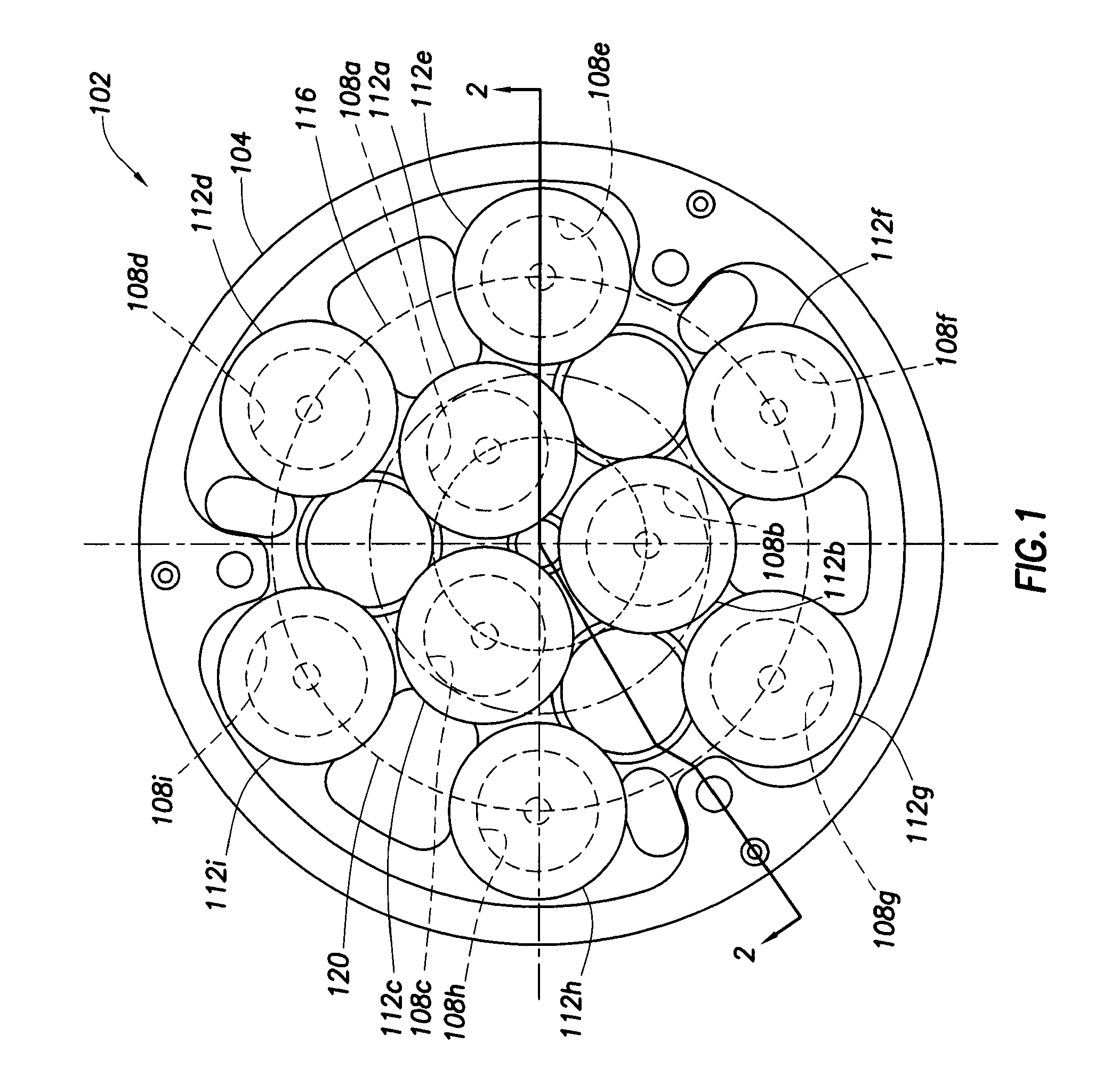
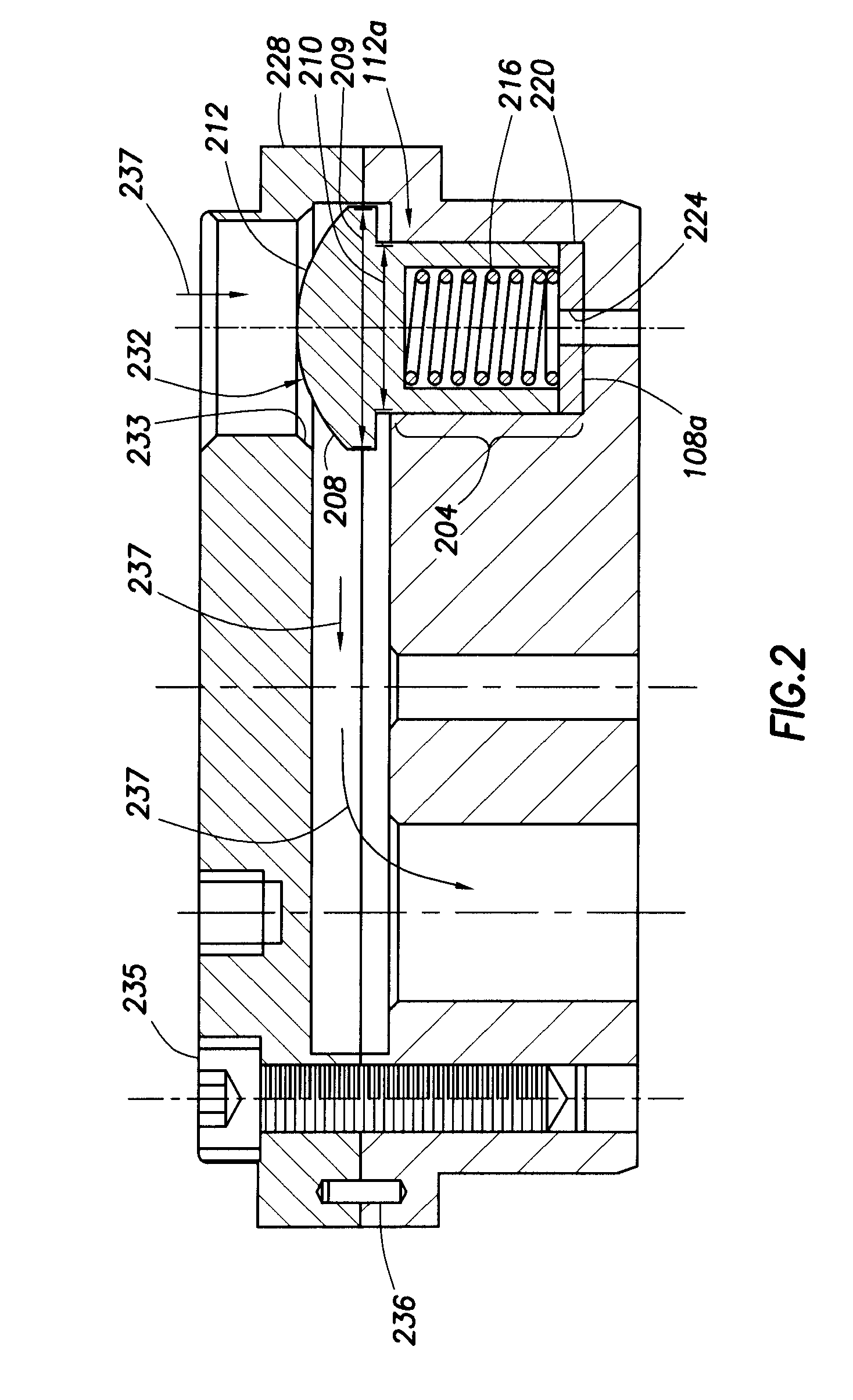
[0013]Referring to FIG. 1, a top view of a poppet valve assembly 102 in accordance with an embodiment of the present disclosure is shown. The poppet valve ...


PUM


Abstract

A poppet valve assembly for a high-speed compressor, the poppet valve assembly including a cage that includes a plurality of counter bores disposed therein. The poppet valve assembly further includes a plurality of poppets, each poppet having a stem and a head. The head of each poppet has a maximum diameter that is less than approximately 0.75 inches. The stem of the poppet is disposed in each of said counter bores. The poppet valve assembly also includes a seat plate overlying said cage, said seat plate including a plurality of through bores axially aligned with the counter bores of the cage. Each through bore is sized to have a smaller diameter than the maximum diameter of the head. A lift spacer is disposed in each of the counter bores.

Description

CROSS-REFERENCE TO RELATED APPLICATIONS[0001]This application claims priority from U.S. provisional patent application No. 61 / 194,882, filed on Oct. 1, 2008 in the U.S. Intellectual Property Office, the disclosure of which is incorporated herein by reference in its entirety.BACKGROUND OF THE INVENTION[0002]1. Field of the Invention[0003]The present invention relates to high-speed compressors, and more particularly, to control of gas flow in high-speed compressors utilizing a poppet valve assembly.[0004]2. Description of the Prior Art[0005]Gas valve assemblies for conventional compressors, namely those operating at between approximately 200 rpm and approximately 600 rpm, often include poppets that have a head diameter ranging from approximately 1 inch to approximately 1 and ⅛ inches. Typically, such systems utilize approximately two to four poppets with heads in this size range to control fluid flow within these compressors. The size of such conventional poppets in the valve assembli...

Claims


Application Information

Patent Timeline
IPC IPC(8): F16K1/00
CPCF04B39/1013
Inventor THOMPSON, GENE M.JONES, CATHERINE
Owner COMPRESSOR ENG CORP
Why Eureka
Try Eureka